Email: store@creasol.it - Telegram: CreasolTech - Whatsapp: +393283730010

Priority mail: fast and cheap - Express Courier: fast and safe

Before returning products, please contact us
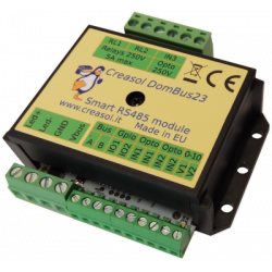
Connect more I/O and sensors to Domoticz using Creasol DomESP1.
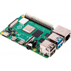
Creasol DomESP1 board is designed for ESP8266 module NodeMCU V3, with 900 mils header pitch (optionally 1100mils header pitch and WeMos D1 mini modules), and integrates the whole circuitry to manage digital inputs, one analog input, 4 relay outputs, 1 low voltage output, I2C bus, 1wire bus and 2 MOSFET outputs.
Full support: most products are designed by us!
Email: store@creasol.it - Telegram: CreasolTech - Whatsapp: +393283730010
Orders are shipped within 1 working day
Priority mail: fast and cheap - Express Courier: fast and safe
24 months warranty, easy return/refund in case of problem
Before returning products, please contact us
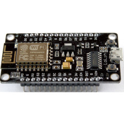
ESP8266 is a very powerful and cheap MCU equipped with WiFi transceiver, very useful to expand inputs/outputs of a domotic system.
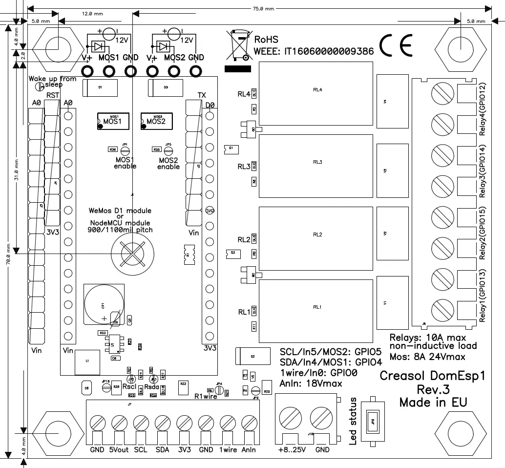
Creasol DomESP1 board is designed for ESP8266 module NodeMCU V3, with 900 mils header pitch (optionally, soldering additional headers, it's possible to use the 1100mils module or WeMos D1 mini module), and integrates the whole circuitry to manage digital inputs, one analog input, 4 relay outputs, I2C bus, 1wire bus and 2 mosfet outputs with 8A 30Vmax capability.
Mosfet outputs are shared with I2C GPIOs, so it's not possible to control both I2C bus and Mosfet!
Please check the English page to have the most up-to-date version.
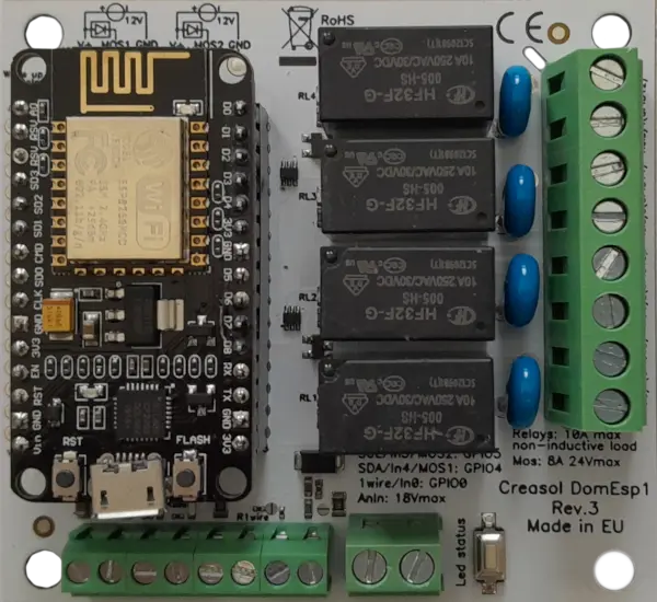 The LEDs on I2C ports and relay outputs, permit to check the status of the board and found any problem on wire connections or firmware configuration: LEDs are enabled by pressing the button Test .
The LEDs enable feature and the switching mode power supply lead to a full control of inputs/outputs with an optimized power consumption, even if ESP8266 module and firmware are not designed to be really "green".
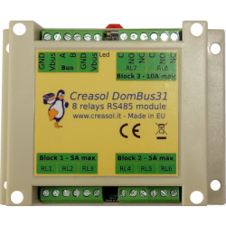
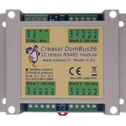
Each relay consumes about 450mW power: if several relays are needed, its recommended to use a smarter devices like Creasol DomBus31 that has 6x 250V 5A SPST relay outputs + 2x 10A SPDT relay outputs: DomBus31 consumes less than 15mW in standby and less than 600mW with all 8 relays ON!
ESP8266 module can be programmed with ESPEasy firmware or another firmware suitable for NodeMCU v3 module, like ESPHome, Tasmota, ...
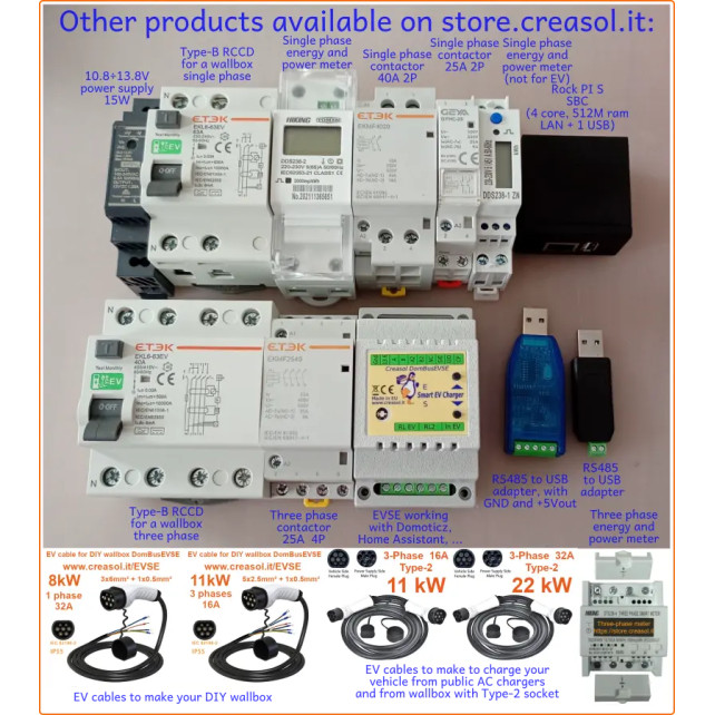
On our store, it's possible to purchase:
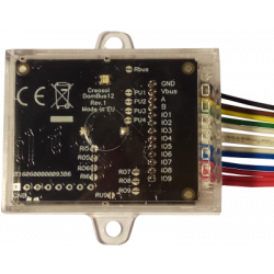
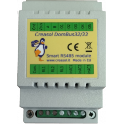
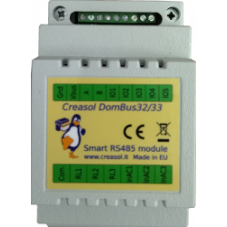
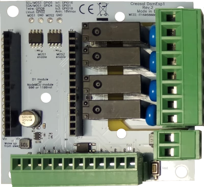
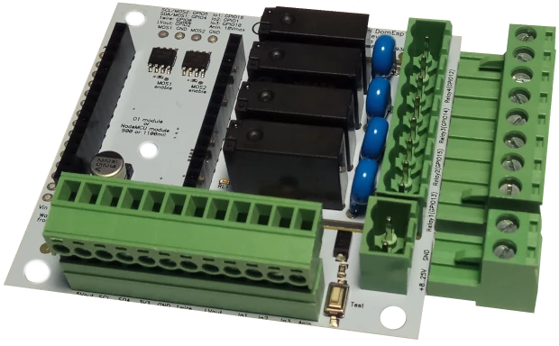
Behind DomESP1 board it's available DomESP2 board: it's exactly the same board, but using plugin terminal blocks (see the picture below).
Do you want more for your home automation system? Discover the DomBus modules:
It's possible to find documentation of the installation process (firmware download, and device configuration) at the address https://www.creasol.it/domesp1conf
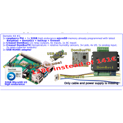
When DomESP1 board is purchased with the NodeMCU module, the firmware ESP-Easy firmware, normal version, has been programmed in the module so it's ready to use.
It's possible to reprogram another kind of firmware (Tasmota, ESPHome, ...), of course.
To access the ESP Easy firmware, follow the steps below:

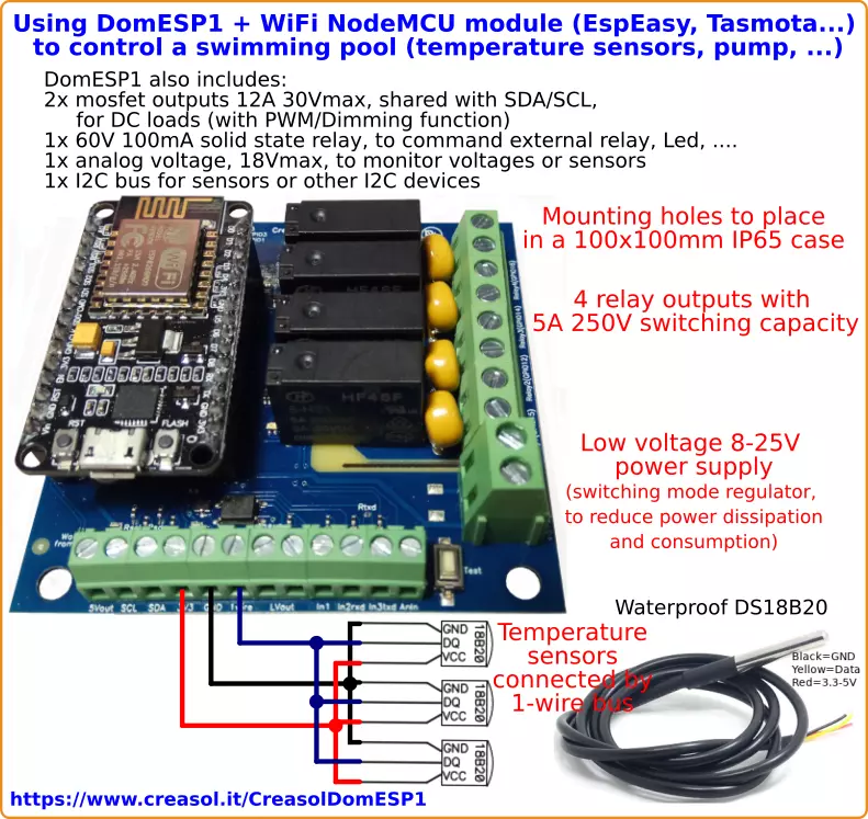
The board is perfect to control pumps and temperature sensors, by using a NodeMCU WiFi module with ESPEasy or Tasmota firmware.
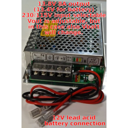
Board is supplied at low voltage, from 8 to 25Vdc, to guarantee the galvanic isolation from the grid: DomESP1 uses a switching mode regulator to minimize the power consumption and dissipation, very useful considering that NodeMCU module consumes 400mW when operative.
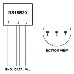
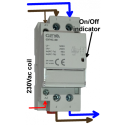
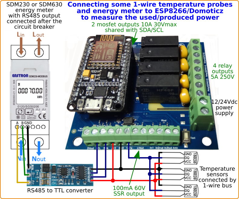
It has 4 relays with 5A 250V capability that can be used to command up to 4 actuators (pump, lights, ...), and supports 1wire bus to connect 1 or more DS18B20 waterproof temperature sensors (in parallel).
Also, it integrates 2 mosfets with 30V 12A capability to control DC loads (with PWM/dimming function), 1 solid state relay with 60V 100mA capability, I²C bus for sensors, and 1 analog input 18V max.
With the following script it's possible to control the swimming pool water temperature, using a black solar pipe and pump to recirculate hot water to increase the water tempeature to the desired set point.
--Domoticz script to control swimming pool water temperature
-- script executed every minute: name this file scripts/lua/script_time_swimmingpool.lua
DEVPUMP="name of pump device"
DEVTEMPA="name of temperature A"
DEVTEMPB="name of temperature B"
TEMPSET=30   -- temperature for the pool

commandArray={}	-- list of command to sent to Domoticz when script ends
tempA=tonumber(otherdevices[DEVTEMPA])
tempB=tonumber(otherdevices[DEVTEMPB])
if (otherdevices[DEVPUMP]=='Off') then
	-- pump is OFF
	if (tempAtempA+5) then
		-- must heat! tempB is 5 degrees > tempA
		commandArray[DEVPUMP]='On'
	end
else
    -- pump is ON
    if (tempA>TEMPSET or tempB<=tempA) then
    	commandArray[DEVPUMP]='Off'
    end
end
return commandArray
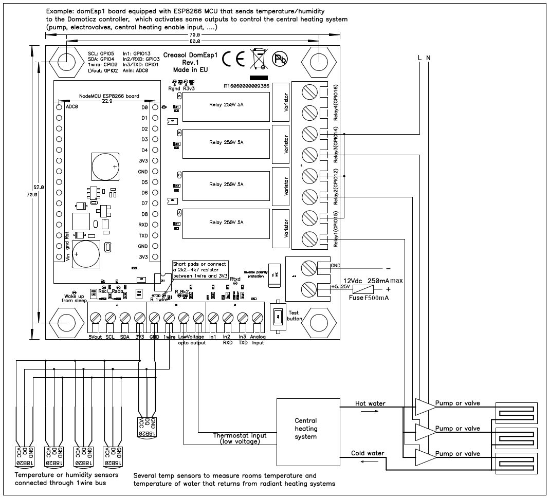
The following diagram shows how to connect some temperature/humidity sensors by 1wire bus to monitor room and water temperatures; ESP8266 controls one low voltage output to enable/disable the heating system, and 3 outputs to enable/disable 3 pumps or valves.
This is just an example. Through the WiFi connection, the ESP8266 module installed on this board will communicate temperatures to Domoticz controller, which will enable/disable the central heating system controlling the 3 heating zones by enabling/disabling the corresponding pump.
To save more energy consumption, we suggest to use DomBus37 or DomBus38, that have relays to manage the heater / heat pump and many inputs to measure temperature. DomBus37 - DomBus38 relays consume 50÷100mW / each, when ON.
For the best power saving, we suggest to use DomBus21, that has 3 high power relays (3.5kW max) that consume nothing when ON or OFF, and 2 inputs that can be used to measure temperature.
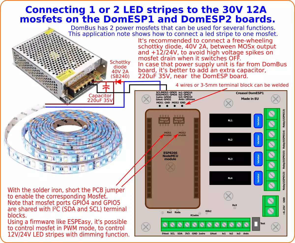
DomESP1 and DomESP2 boards have 2 mosfets, 30V 12A, that can be used for serveral different functions.
In this application note we'll describe how to control one or two 12/24Vdc Led stripes by these mosfets, that can be activated as ON/OFF or as PWM for dimming.
Using EspEasy firmware on ESP8266 module, it's possible to control the PWM output by a http call, using the syntax
http://IP_OF_ESP_MODULE/control?cmd=pwm,GPIO,DUTY_CYCLE,FADING_TIME
for example
http://192.168.1.123/control?cmd=pwm,4,512,1000
to set pwm on GPIO 4 (output MOS1), duty cycle to 50% (value varies from 0=Off to 1023=On), using a fading time of 1000ms (so the duty cycle changes gradually to the set value in 1 second).
In Domoticz it's possible to create a virtual switch that can be set (in the Switchs panel) as SwitchType=Dimmer, then you can find a slidebar that can be moved from 0 to 100%. To output this percentage value on EspEasy it's neccessary to follow the instructions at https://www.domoticz.com/forum/viewtopic.php?t=20583
N-Mosfet are connected in open-drain configuration, with source connected to the GND hole, connected togheter to the ground plane of the board, so mosfets are not galvanically separated from the rest of the board.
In the PCB you can find two holes for each mosfet, one marked as MOS1 that have to be connected to the V- terminal of the Led stripe, and one marked as GND that should be connected to the V- terminal of of the power supply. The V+ terminal of the Led strip should be connected to the V+ terminal of the 12/24V power supply. The same for MOS2 and GND holes, connected to the 2nd mosfet. Wires or 3.5mm pitch terminal blocks can be soldered to these 4 pad-holes.
To enable the mosfet output, a jumper in the PCB, marked as MOSx enable, must be shorted by using the solder iron. MOS1 shares the same GPIO of SDA, while MOS2 shares the same GPIO of SCL, so enabling a mosfet you loose the possibility to use SDA or SCL as input/output/I2C.
To prevent high voltage spikes during mosfet switch from ON to OFF, it's recommended to connect an external free-wheeling schottky diode 2A 40V as indicated in the picture. Also, if the power supply is not placed near the DomESP board, it's better to add a 220uF 35V capacitor on power wires, near the DomESP board, to minimize the conducted noise over the power supply wires.

Connect more I/O and sensors to Domoticz using Creasol DomESP1.
Creasol DomESP1 board is designed for ESP8266 module NodeMCU V3, with 900 mils header pitch (optionally 1100mils header pitch and WeMos D1 mini modules), and integrates the whole circuitry to manage digital inputs, one analog input, 4 relay outputs, 1 low voltage output, I2C bus, 1wire bus and 2 MOSFET outputs.