- -30%


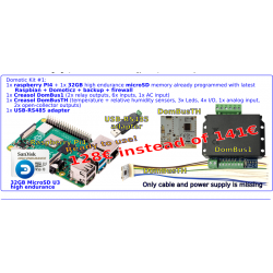
Connect more I/O and sensors to Domoticz using Creasol DomESP1.
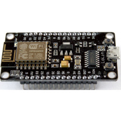
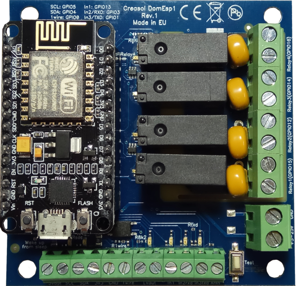
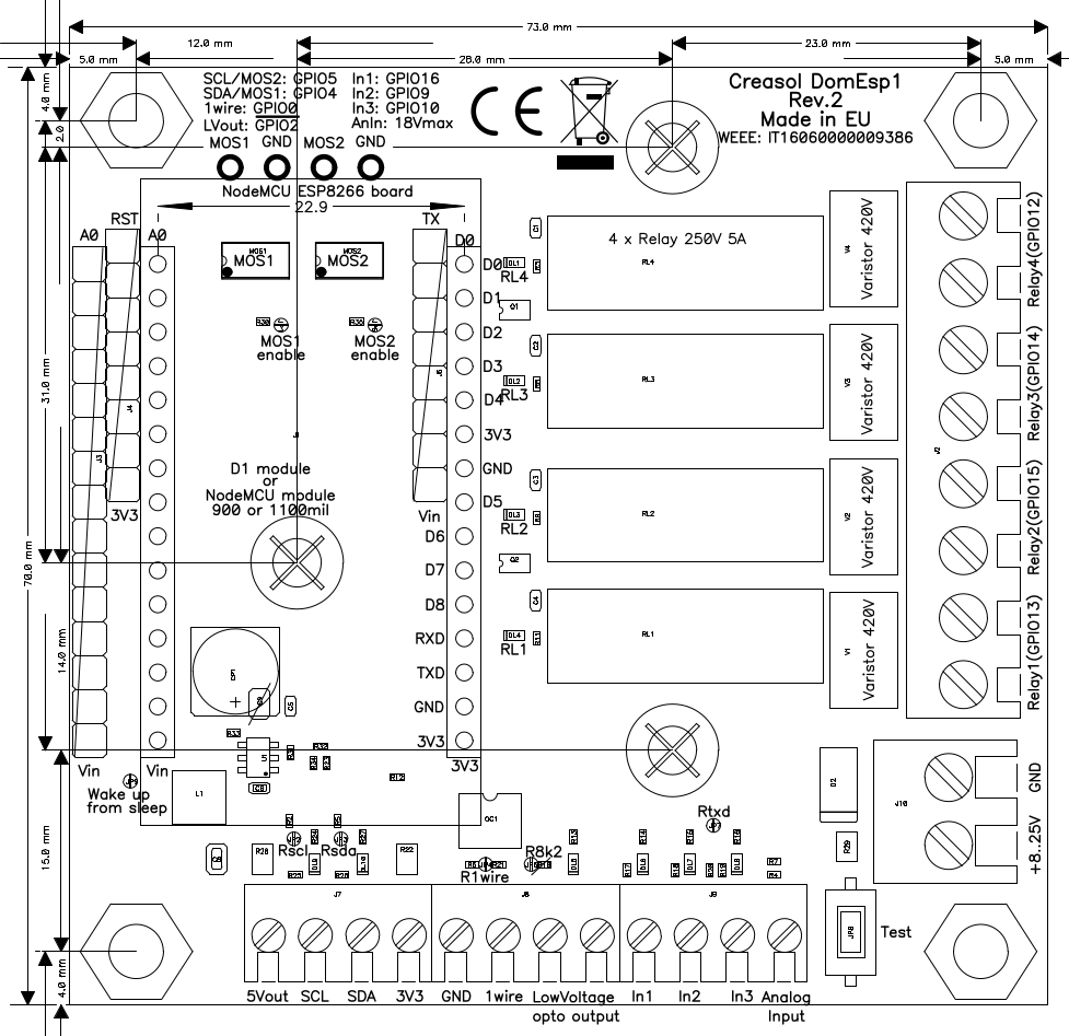
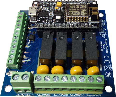
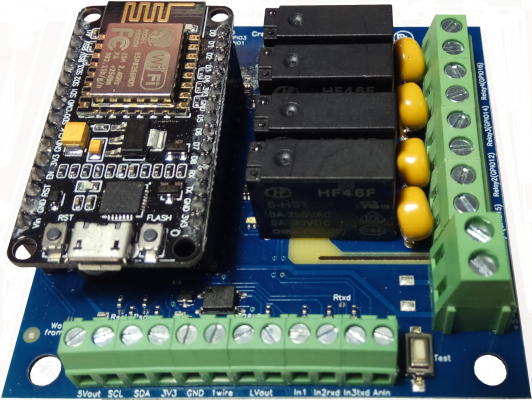
Creasol DomESP1 board is designed for ESP8266 module NodeMCU V3, with 900 mils header pitch (optionally 1100mils header pitch and WeMos D1 mini modules), and integrates the whole circuitry to manage digital inputs, one analog input, 4 relay outputs, 1 low voltage output, I2C bus, 1wire bus and 2 MOSFET outputs.
Also the DomESP2 board is available, using plugin terminal blocks!

Full support: most products are designed by us!

Orders are shipped within 1 working day, by post or express courier

24 months warranty, easy return/refund in case of problem
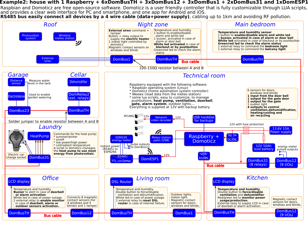
 ESP8266 is a very powerful and cheap MCU equipped with WiFi transceiver, very useful to expand inputs/outputs of a Raspberry/Domoticz controller.
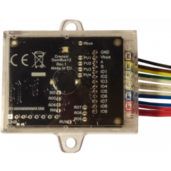
Creasol DomESP1 board is designed for ESP8266 module NodeMCU V3, with 900 mils header pitch (optionally, soldering additional headers, it's possible to use the 1100mils module or WeMos D1 mini module), and integrates the whole circuitry to manage digital inputs, one analog input, 4 relay outputs, 1 low voltage output, I2C bus, 1wire bus and 2 mosfet outputs with 10A 30Vmax capability.
Also the DomESP2 board is available, using plugin terminal blocks!
The LEDs on every input, output and bus, permit to check the status of the board and found any problem on wire connections or firmware configuration: LEDs are enabled by pressing the button Test .
The LEDs enable feature and the switching mode power supply lead to a full control of inputs/outputs with an optimized power consumption, even if ESP8266 module and firmware are not designed to be really "green".
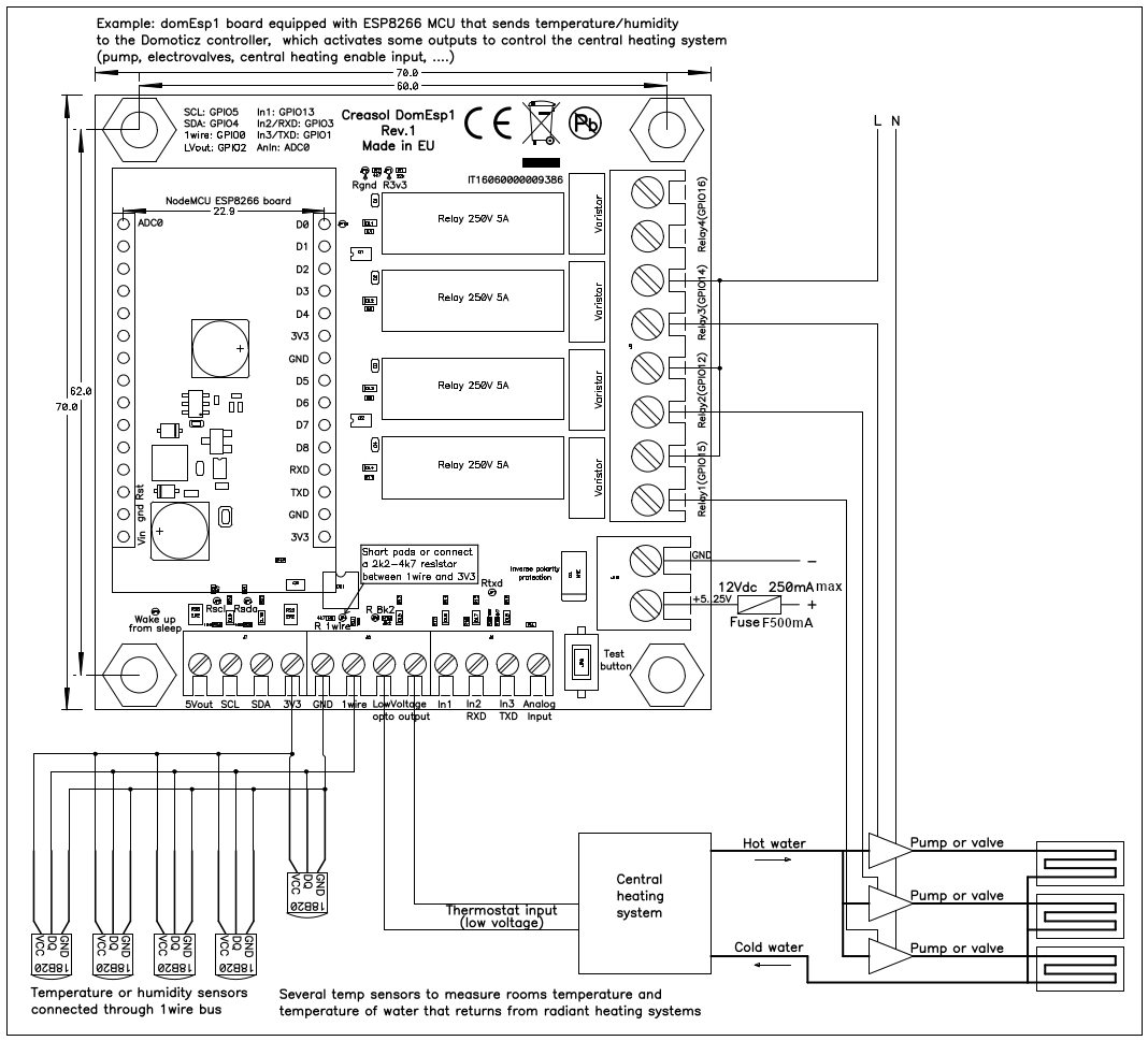
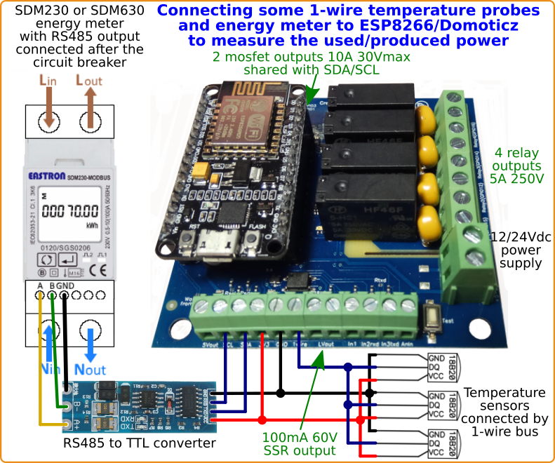
Low voltage output has a Solid State Relay with 100mA 60V capability designed to drive electronic board inputs like boiler on/off input or gate/garage door start command, and consumes only 5mW of power.
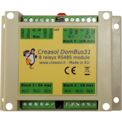
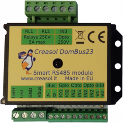
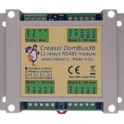
Each relay consumes about 200mW power: if several relays are needed, its recommended to use smarter devices like Creasol DomBus31 that has 6x 5A SPST relay outputs + 2x 10A SPDT relay outputs and each relay consumes less than 50mW of power.
We recommend to program ESP8266 module using ESPEasy firmware, to make it suitable for Domoticz controller, one of the most DIY controllers for home automation systems.
It's possible to purchase:
Any customization you need, please contact us: we normally provide customizations even for small quantities.
It's possible to find documentation of the installation process (firmware download, and device configuration) at the address https://www.creasol.it/domesp1conf
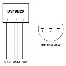
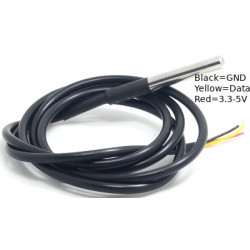
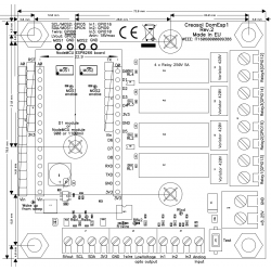
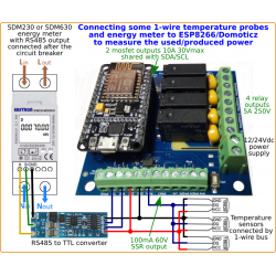
The following diagram shows how to connect some temperature/humidity sensors by 1wire bus to monitor room and water temperatures; ESP8266 controls one low voltage output to enable/disable the heating system, and 3 outputs to enable/disable 3 pumps or valves.
This is just an example. Through the WiFi connection, the ESP8266 module installed on this board will communicate temperatures to Domoticz controller, which will enable/disable the central heating system controlling the 3 heating zones by enabling/disabling the corresponding pump.
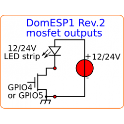
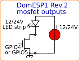 Using the mosfet to control Led strips by PWM
DomESP1 Rev.2 has 2 mosfets, 30V 10A, that can be used to supply 12 or 24Vdc Led strips.
Using EspEasy firmware on ESP8266 module, it's possible to control the PWM output by a http call, using the syntax
http://IP_OF_ESP_MODULE/control?cmd=pwm,GPIO,DUTY_CYCLE,FADING_TIME
for example
http://192.168.1.123/control?cmd=pwm,4,512,1000
to set pwm on GPIO 4 (output MOS1), duty cycle to 50% (value varies from 0=Off to 1023=On), using a fading time of 1000ms (so the duty cycle changes gradually to the set value in 1 second).
In Domoticz it's possible to create a virtual switch that can be set (in the Switchs panel) as SwitchType=Dimmer, then you can find a slidebar that can be moved from 0 to 100%. To output this percentage value on EspEasy it's neccessary to follow the instructions at https://www.domoticz.com/forum/viewtopic.php?t=20583
In the PCB you can find two holes for each mosfet, one marked as MOS1 that have to be connected to the - terminal of the load (Led strip?), and one marked as GND that have to be connected to the - terminal of of the load power supply. Both - terminal of load power supply and DomESP1 power supply will be internally connected together.
To enable a mosfet output, a jumper in the PCB, marked as MOSx enable, must be shorted by using the solder iron. MOS1 shares the same GPIO of SDA, while MOS2 shares the same GPIO of SCL, so enabling a mosfet you loose the possibility to use SDA or SCL as input/output/I2C. Remember to

You might also like

Connect more I/O and sensors to Domoticz using Creasol DomESP1.
Creasol DomESP1 board is designed for ESP8266 module NodeMCU V3, with 900 mils header pitch (optionally 1100mils header pitch and WeMos D1 mini modules), and integrates the whole circuitry to manage digital inputs, one analog input, 4 relay outputs, 1 low voltage output, I2C bus, 1wire bus and 2 MOSFET outputs.
Also the DomESP2 board is available, using plugin terminal blocks!
 Instruction manual