")

Email: store@creasol.it - Telegram: CreasolTech - Whatsapp: +393283730010

Priority mail: fast and cheap - Express Courier: fast and safe

Before returning products, please contact us
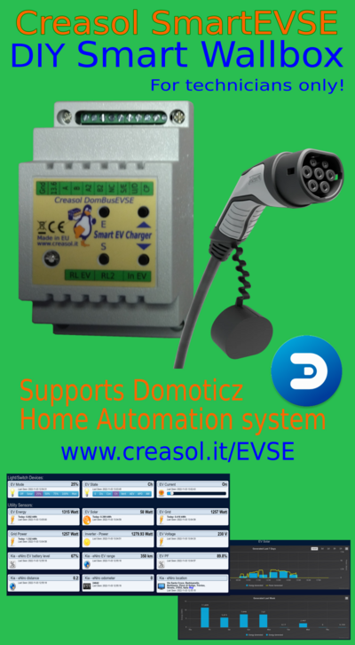
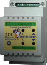
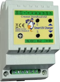
Smart EVSE module to make DIY EV charging station (wallbox) that also works with Domoticz home automation system
Full support: most products are designed by us!
Email: store@creasol.it - Telegram: CreasolTech - Whatsapp: +393283730010
Orders are shipped within 1 working day
Priority mail: fast and cheap - Express Courier: fast and safe
24 months warranty, easy return/refund in case of problem
Before returning products, please contact us
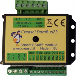
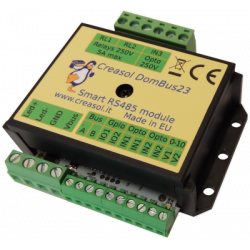
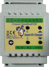
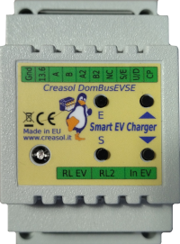
Creasol DomBusEVSE is a fully tested DIN rail module, designed for Domoticz home automation system, to charge electric vehicles using the standard IEC 62196-2 Mode3 (AC charge, up to 22kW power).
It works as stand-alone (without any domotic controller) or in managed mode (charging current controlled by Domoticz).
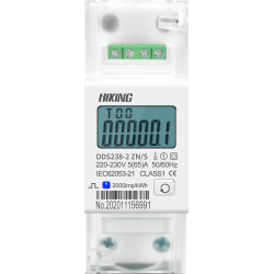
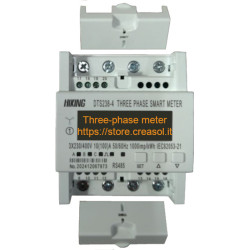
In stand-alone mode it works only as single-phase charger, because it's able to read only DDS238-2 ZN/S energy meter (single phase); using Domoticz home automation, it's able to manage three-phase charging by getting the current grid power value from Domoticz (e.g. SDM630 or other power meter already installed in Domoticz). The power value from the electricity grid is needed by DomBusEVSE to regulate the charging current preventing overloads/disconnections, and also to keep the max power set by the user: more info below.
Although this is a fully tested product, it may be used by technical engineers only for development or demostration. Creasol declines all responsibility for damage to things or people.
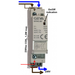
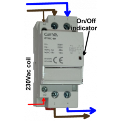
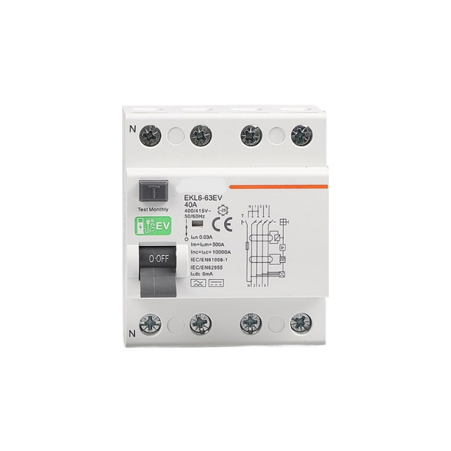
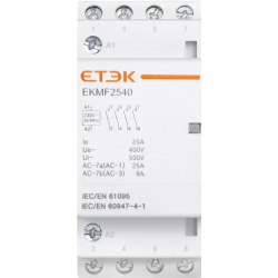
Mains power supply (230V single-phase, 400V three-phase) is connected to the vehicle through a 2P or 4P contactor (relays) to assure that no power is applied when charging session is OFF.
Only the Control Pilot wire + earth/ground are connected to the EVSE module: control pilot is protected by transient voltage suppression device.
A smart EVSE module:
With Domoticz, it's also possible to connect the vehicle cloud to get other informations about battery state of charge, odometer, location, speed, ...
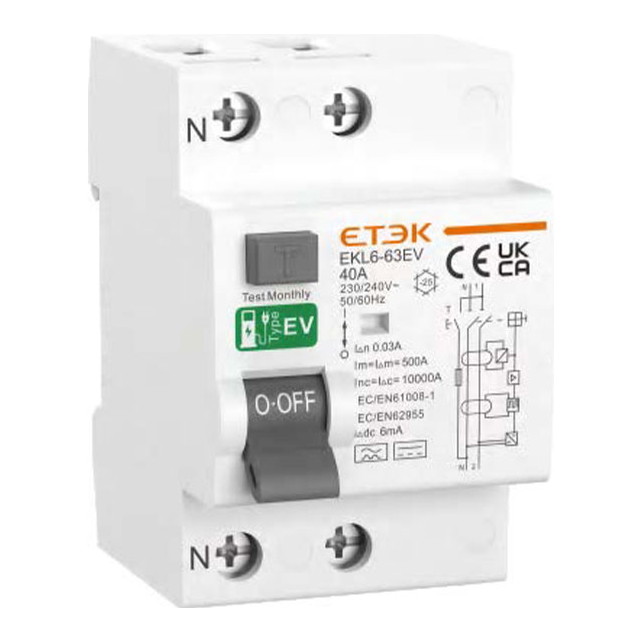
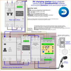
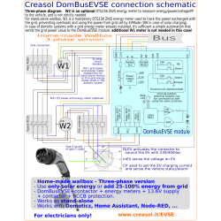
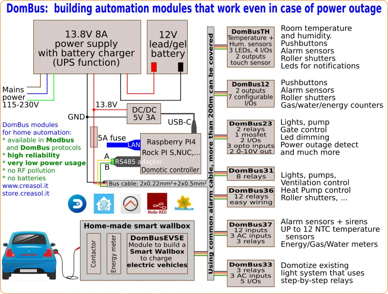
The following diagram shows the connection of the EVSE module to energy meter, contactor, RCD to get a complete smart wallbox, single-phase 230V, sensing the grid power to get the best charging speed preventing overloads and disconnections. Block diagram is available also in PDF format.
It's possible to make a three phase charger by replacing the contactor with a 4P version and using an three-phase energy meter connected to Domoticz so the current power drained from the electricity grid is fed by Domoticz to the DomBusEVSE module.
This device was designed for technical engineers only, for developing purpose. Creasol declines any responsibility for damage to things or people.
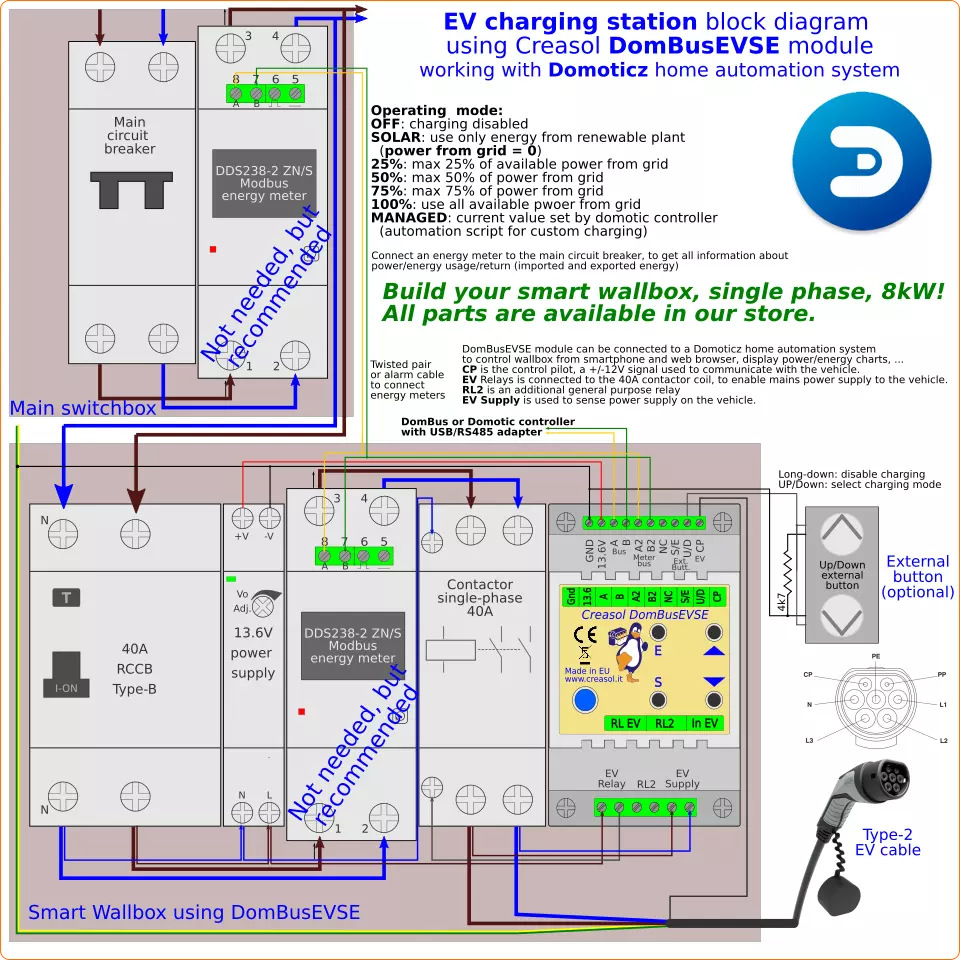
Make all wirings as indicated in the diagram above (click to get the PDF schematic with higher resolution), but connect only the energy meter that measures energy to the electric vehicle.
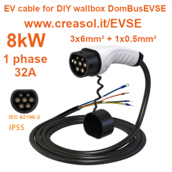
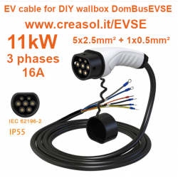
We suggest to put the wallbox modules in a indoor switchbox, possibly near the point where you'll park your car, but also near the main switchbox or solar inverter, if exists, to minimize cable length: use 6mm² (or 10mm²) wires for the mains power supply. Then place a small 10x10cm box where the electric car is parked, indoor or outdoor, connected by 3x 6mm² (or 10mm²) wires (L,N,PE) plus a shielded 2x0.22mm² cable (standard cable for alarm systems): one wire is connected to the CP terminal block (control pilot), and other wire + shield are connected to PE/GND. The Type-2 or Type-1 cable (with only plug connector to the vehicle) will be connected to the small box.
In case that device is used as stand-alone, without attached domotic controller, energy meters must be already configured with Modbus address=2 (to EV) and address=3 (to Grid): they can be purchased from Creasol Store asking to get address already programmed. Also it's possible to ask that EVSE module is preprogrammed with the right value of MAXPOWER (max power from grid), MAXCURRENT (max current supported by the EV cable).
The next instructions are relative to Domoticz controller, a free open-source home automation controller that let a full control of the wallbox and is highly recommended: it works in cheap hardware like Rock PI-S or Raspberry PI4, as like Linux computers, windows and Mac.
It's recommended to install Domoticz Beta, which is up-to-date, Python Plugin Manager (not available in Windows), then it's possible to install the Creasol DomBus plugin from Python Plugin Manager: in this way it's possible to get notifications about future updates of the DomBus plugin, and auto upgrade.
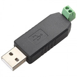
DomBusEVSE can be connected to the domotic controller / PC by a USB/RS485 adapter: a device will be automatically added to Domoticz -> Switches panel, with factory-default address ffe3.1: click on Edit button and add to the Description ,HWADDR=0x0001 or other unique address, then click Save button: click on Dashboard and then on Switches again to see, in the bottom, the EVSE devices: EVSE On, RL2, EVSE Supply, EVSE Mode, EVSE State, EVSE Current. Click on EVSE Mode, and edit the MAXPOWER and MAXCURRENT parameters, then save.
Create a new room to group all EVSE device: Setup -> More Options -> Plans -> Room Plan, add a new room Wallbox or something else, and add all devices with address corresponding with the HWADDR set before. Then, click on Dashboard and select the Wallbox room.
As energy meters are factory programmed with Modbus address 1, first connect the energy meter between Type-B RCCB and contactor, and assign address = 2 in this way: select Domoticz -> Utility -> M1 Addr device, click on Edit button and write in the Description field ,ADDR=2 then save. Then connect the main energy meter (that measure the power exchanged with the grid) and assign address=2: select Domoticz -> Utility -> M1 Addr device, click on Edit button and write in the Description field ,ADDR=3 then save.
If a energy meter connected to the electricity grid is already available, it's sufficient to install a simple script that, when the power from grid changes, update the value of the "virtual device" Grid Power that is automatically created
Finally, DomBusEVSE has additional support for:
* SPST relay output RL2, with 250V 5A capability, that can be used for any purpose
* up to 4 energy meters, so 2 additionally energy meters (with address=4 and 5) can be connected to get power statistics for the heat pump, kitchen, ....
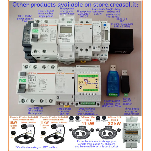
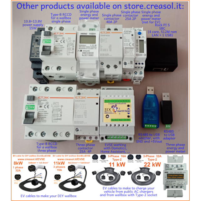
All parts should be available in the Creasol Store, but not the Type-2 or Type-1 cable.
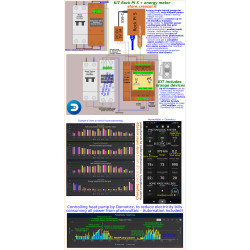
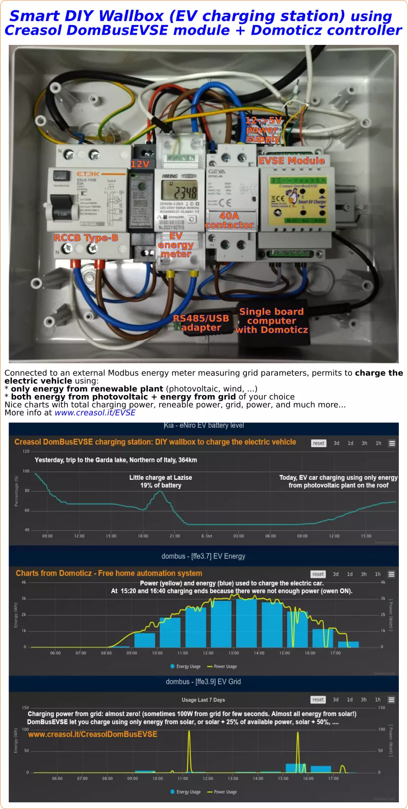
The following picture shows the integration in Domoticz of the EV (Kia Niro car, using the plugin available with Python Plugin Manager) and DomBusEVSE module; it shows a trip to Garda Lake, Northern of Italy, with a short charging session at a 11kW station, and then a long charging session using DomBusEVSE wallbox in SOLAR mode (only energy from photovoltic).
During the charging session at home, in SOLAR mode, both the washer machine and the oven were switched on: in this cases the EVSE module reduced the charging current to the minimum and after 90 seconds ended the session until available power returned above the STARTPOWER parameter. As displayed in the charts below, the module assure that no power comes from the grid, in SOLAR mode.
When DomBusEVSE module is configured in managed mode, Domoticz is responsible to set the charging current as preferred. Obviously, all protections regarding max current, min current and any alarms from the car are correctly managed by the EVSE module.
In managed mode it's easy to:
1. easily set the minimum and maximum battery level
2. easily set the maximum charging current
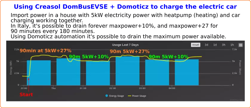
3. when battery level is below minimum, charge at the max power permitted by the electricity meter (in Italy, alternates 90 minutes at maximum power + 27% and 90 minutes at maximum power + 10%, it's not possible to charge faster! The electrical system must be checked carefully when using maximum power, to avoid overheating and fires!!)
4. when battery level is between minimum and maximum, charge using only power from renewable energy from photovoltaic
Also, the max grid power can be adjusted to get the maximum from the grid. The chart below shows the case of Italy, where the max available power is P+10% forever, and P+27% for max 90 minutes every 180 minutes: charging power will be the highest as possible, regulating the charging power to get the maximum available power preventing disconnections. Charging power is updated every 6 seconds to take care about other building appliances.
{youtube}fyDtGO6S1UI{/youtube}
In case that a stationary accumulator is installed in the building, two cases are possible:
1. the DomBusEVSE grid energy meter is installed before the stationary accumulator/inverter sensor (mains power supply -> DomBusEVSE energy meter -> battery sensor)
2. the DomBusEVSE grid energy meter is installed after the stationary accumulator/inverter sensor (mains power supply -> battery sensor -> DomBusEVSE energy meter)
To explain these two cases, let assume that photovoltaic is producing 3kW, house is consuming 1kW, max power from battery is 5kW, max power from grid is 6kW
| EVSE Mode | OFF | SOLAR | 25% | 50% | 75% | 100% |
| Case #1 charging power (EVSE meter, then battery meter) |
0 | 3-1=2kW | 3-1+1.5=3.5kW | 3-1+3=5kW | 3-1+4.5=6.5kW | 3-1+6=8kW |
| Case #2 charging power (battery meter, then EVSE meter) |
0 | 3-1+5=7kW | 3-1+5+1.5=8.5kW | 3-1+5+3=10kW | 3-1+5+4.5=11.5kW | 3-1+5+6=13kW |
Obviously, a parameter set the max current supported by the cable, that usually is 32A, so the charging power is limited to 7-8kW in single phase.
The following video shows a presentation of some domotic modules designed and produced in Italy by Creasol to make a reliable, easy and power-optimized home automation system.
The next video shows our Smart EVSE module that can be used to charge the electric car by using only solar power, or adding 25/50/75/100% of available power from the electrical grid.
Our industrial and home automation modules are designed to be
Modules are available in two version:
Store website - Information website
For our products we can offer FULL SUPPORT and CUSTOMIZATION: please contact us by Email or Telegram
 Complete solution to make a Smart EVSE, charging the electric vehicle using only energy from renewable source (photovoltaic, wind, ...), or adding 25-50-75-100% of available power from the grid.
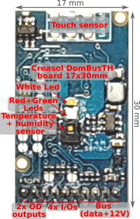 Compact board, 32x17mm, to be installed on blank cover with a 4mm hole in the middle, to exchange air for the relative humidity sensor. It can be installed in every room to monitor temperature and humidity, check alarm sensors, control blind motor UP/DOWN, send notifications (using red and green leds) and activate white led in case of power outage.
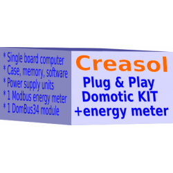
Includes:
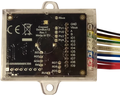 Very compact, versatile and cost-effective module with 9 ports. Each port can be configured by software as:
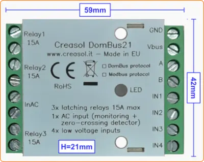 Very low power consumption module designed to enable up to 3 high power loads, up to 15A (3kW).
 Versatile module designed to control gate or garage door.
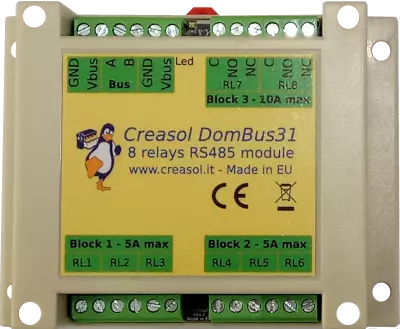 DIN rail low profile module, with 8 relays and very low power consumption:
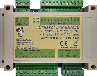
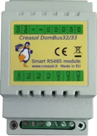 Versatile module with 230V inputs and outputs, and 5 low voltage I/Os.
Module designed to control 3 lights already existing and actually controlled by 230V pushbuttons and step-by-step relays. In this way each light can be activated by existing pushbuttons, and by the domotic controller.
Each relay can toggle the existing step-relay, switching the light On/Off. The optoisolator monitors the light status. The 5 I/Os can be connected to pushbuttons to activate or deactivate one or all lights.
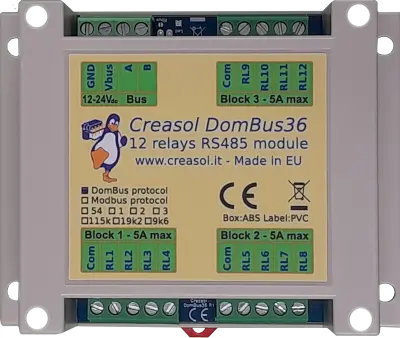 DIN rail module, low profile, with 12 relays outputs and very low power consumption.
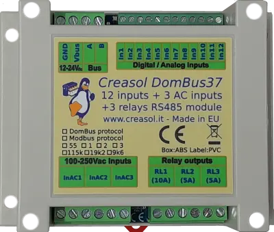 Module designed to be connected to alarm sensors (magnetc contact sensors, PIRs, tampers): it's able to monitor mains power supply (power outage / blackout) and also have 3 relays outputs.
 DIN rail module designed for burglar alarm system.
![]() DIN rail module that control azimuth + elevation/tilt motors of a sun tracker, to maximize photovoltaic energy production during the day and seasons.
DIN rail module that control azimuth + elevation/tilt motors of a sun tracker, to maximize photovoltaic energy production during the day and seasons.
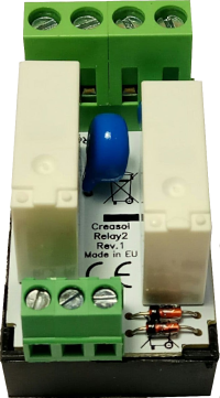 Simple module with 2 relays, to be used with DomBus modules or other electronic boards with open-collector or open-drain outputs
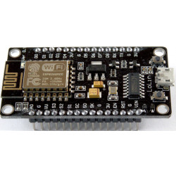
 IoT board designed for NodeMCU v3 board using ESP8266 WiFi microcontroller

The perfect match
Module works perfect with modbus connection to Loxone domotics via esphome RS485 interface.
Commands are send by Loxone with HTTP rest api to Lilygo RS485.
Cheap solution for DIY car charger. Thumbs up.
J'utilise HomeAssistant.
Très bien!
Utilizo este módulo con Home Assistant para recargar mi ID.4.
Funciona bien, muy inteligente
Smart EVSE module to make DIY EV charging station (wallbox) that also works with Domoticz home automation system