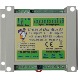
Reliable low-power domotic module designed to enable/disable loads saving energy consumption, zeroing the standby power.
It uses 3 latching relays, 15A 250Vac, that does not consume anything when are active, and can be used to enable loads or generators up to 3kW that are OFF for long time. Also, removing power to loads during lightning storms helps prevent damage from electrostatic discharges.
It also have 1 AC input to sense 230Vac voltage (detecting power outage), that acts also as a zero-crossing detector that permits to enable relays when voltage is zero (to minimize in-rush current, in case of capacitive loads) and disable relays when current in zero (to minimize overvoltage in case of inductive loads).
4 low voltage inputs, that can be configured as analog or digital, permit to connect pushbutton switches, NTC thermal probes, alarm sensors and energy / gas / water meters with pulsed output.
The 3 latching relays can be used to enable/disable:
heat pump, that normally consumes more than 5W in standby
boiler, heater or other appliances consuming power in standby
gate and garage door, that normally consumes more than 5W/each in standby, and it's also good to disable them when away alarm is active to prevent thefts.
small photovoltaic systems, less than 3kWp
outdoor lights
Features
3x 15A SPST latching relays, that permit to manage up to 3kW loads or generators 230Vac
1x AC input, 100-250V, that is used for two functions: zero-crossing detector + voltage presence
4x configurable low voltage inputs, analog or digital: each input, using GND as common voltage, can be configured as pushbutton, twinbutton (UP/DOWN buttons that uses a single input), alarm sensor (magnetic, PIR, ...), NTC 10k thermal sensor, counter / meter with pulsed output.
only 15mW power consumption, even if one or more relays are ON.
available with two firmwares (you have to choose the best one for you!):
DomBus firmware, supporting the proprietary DomBus protocol, working with Domoticz
Modbus firmware, supporting the standard Modbus RTU protocol, working with Home Assistant, OpenHAB, NodeRED, ...
RS485 bus connection, industrial grade, 115200bps, permitting to use up to 500m of standard alarm cable (2x0.5mm² + 2x0.22mm² + shield) for connections.
Very compact size: 59x42x21mm, fits everywhere, expecially in switchboxes and junction boxes.
DomBus21 ports capabilities (for the DomBus version)
Default address: 0xff21
Port#
Name
Capabilities
Default configuration
Description
1
RL1
OUT_DIGITAL
OUT_DIGITAL
SPST 15A latching relay: coil is activated only during on/off transitions, consuming nothing when relay is ON or OFF. The INAC input should be connected to 230Vac to permit the zero-crossing detection, avoiding high in-rush current (for capacitive loads) and overvoltage (for inductive loads)
2
RL2
OUT_DIGITAL
OUT_DIGITAL
SPST 15A latching relay: coil is activated only during on/off transitions, consuming nothing when relay is ON or OFF. The INAC input should be connected to 230Vac to permit the zero-crossing detection, avoiding high in-rush current (for capacitive loads) and overvoltage (for inductive loads)
3
RL3
OUT_DIGITAL
OUT_DIGITAL
SPST 15A latching relay: coil is activated only during on/off transitions, consuming nothing when relay is ON or OFF. The INAC input should be connected to 230Vac to permit the zero-crossing detection, avoiding high in-rush current (for capacitive loads) and overvoltage (for inductive loads)
4
INAC
IN_AC, IN_COUNTER
IN_AC
Optoisolated input, that can be connected to a circuit breaker (to notify power outages, expecially for fridges and heat pumps), PIRs with 230V output (to monitor presence), light and appliances (to monitor when light or devices are ON).
Analog or digital input, with optional 10k pullup (pcb jumper) and optional internal pulldown (activated when configured as IN_DIGITAL_PULLDOWN). Common terminal block is GND: pushbutton, switch, twinbutton (double button with 10k resistor between buttons), alarm sensor, 10k NTC thermistor, counter with pulsed output (energy meter, gas meter, water flow meter), ... should be connected to this input and to GND.
Analog or digital input, with optional 10k pullup (pcb jumper) and optional internal pulldown (activated when configured as IN_DIGITAL_PULLDOWN). Common terminal block is GND: pushbutton, switch, twinbutton (double button with 10k resistor between buttons), alarm sensor, 10k NTC thermistor, counter with pulsed output (energy meter, gas meter, water flow meter), ... should be connected to this input and to GND.
Analog or digital input, with internal pullup or pulldown (activated when configured as IN_DIGITAL_PULLDOWN). Common terminal block is GND: pushbutton, switch, alarm sensor, counter with pulsed output (energy meter, gas meter, water flow meter), ... should be connected to this input and to GND.
Analog or digital input, with internal pullup or pulldown (activated when configured as IN_DIGITAL_PULLDOWN). Common terminal block is GND: pushbutton, switch, alarm sensor, counter with pulsed output (energy meter, gas meter, water flow meter), ... should be connected to this input and to GND.
DomBus21 Modbus RTU capabilities (for the Modbus version)
At power-on, the module shows on red LED the current Modbus slave address (register address=8192) in decimal format, on green LED the serial baudrate (reg. 8193), and finally on red LED the serial parity (reg. 8194). If a value is zero, a long flash is emitted.
For example, if reg(8192)=33, reg(8193)=0, reg(8194)=0, at power the following led flashes will be shown: 3 red flashes, pause, 3 red flashes (slave address= 0x21 = 33 decimal), pause, 1 long green flash (reg(8193)=0 => baudrate=115200bps), pause, 1 long red flash (reg(8194)=0 => parity=None).
Device will be operative only when address/baudrate/parity parameters have been shown: then module will accept commands by Modbus RTU, and periodically shows output status for all ports, from 1 to max port: green flash means that port status is Off, red flash means that port is On.
Default slave address: 33 (0x21)
Addr
Name
Values
Description
0
RL1
0=OFF, 1 or 65280=ON, 2-65279=ON for specified time. Logic can be inverted specifying the INVERTED option (on address 512+port)
SPST 15A latching relay: coil is activated only during on/off transitions, consuming nothing when relay is ON or OFF. The INAC input should be connected to 230Vac to permit the zero-crossing detection, avoiding high in-rush current (for capacitive loads) and overvoltage (for inductive loads)
1
RL2
0=OFF, 1 or 65280=ON, 2-65279=ON for specified time. Logic can be inverted specifying the INVERTED option (on address 512+port)
SPST 15A latching relay: coil is activated only during on/off transitions, consuming nothing when relay is ON or OFF. The INAC input should be connected to 230Vac to permit the zero-crossing detection, avoiding high in-rush current (for capacitive loads) and overvoltage (for inductive loads)
2
RL3
0=OFF, 1 or 65280=ON, 2-65279=ON for specified time. Logic can be inverted specifying the INVERTED option (on address 512+port)
SPST 15A latching relay: coil is activated only during on/off transitions, consuming nothing when relay is ON or OFF. The INAC input should be connected to 230Vac to permit the zero-crossing detection, avoiding high in-rush current (for capacitive loads) and overvoltage (for inductive loads)
3
INAC
0=OFF (floating), 1=ON (100-250V signal detected)
Optoisolated input, that can be connected to a circuit breaker (to notify power outages, expecially for fridges and heat pumps), PIRs with 230V output (to monitor presence), light and appliances (to monitor when light or devices are ON).
4
IN1
0=OFF, 1=ON, or 0-65535 if port is configured as analog. See below for more information.
Analog or digital input, with optional 10k pullup (pcb jumper) and optional internal pulldown (activated when configured as IN_DIGITAL_PULLDOWN). Common terminal block is GND: pushbutton, switch, twinbutton (double button with 10k resistor between buttons), alarm sensor, 10k NTC thermistor, counter with pulsed output (energy meter, gas meter, water flow meter), ... should be connected to this input and to GND.
5
IN2
0=OFF, 1=ON, or 0-65535 if port is configured as analog. See below for more information.
Analog or digital input, with optional 10k pullup (pcb jumper) and optional internal pulldown (activated when configured as IN_DIGITAL_PULLDOWN). Common terminal block is GND: pushbutton, switch, twinbutton (double button with 10k resistor between buttons), alarm sensor, 10k NTC thermistor, counter with pulsed output (energy meter, gas meter, water flow meter), ... should be connected to this input and to GND.
6
IN3
0=OFF, 1=ON, or 0-65535 if port is configured as analog. See below for more information.
Analog or digital input, with internal pullup or pulldown (activated when configured as IN_DIGITAL_PULLDOWN). Common terminal block is GND: pushbutton, switch, alarm sensor, counter with pulsed output (energy meter, gas meter, water flow meter), ... should be connected to this input and to GND.
7
IN4
0=OFF, 1=ON, or 0-65535 if port is configured as analog. See below for more information.
Analog or digital input, with internal pullup or pulldown (activated when configured as IN_DIGITAL_PULLDOWN). Common terminal block is GND: pushbutton, switch, alarm sensor, counter with pulsed output (energy meter, gas meter, water flow meter), ... should be connected to this input and to GND.
256-273
Port config
1=OUT_DIGITAL, 2=OUT_RELAY_LP, ...
Command used to configure port 1 (256), port 2 (257), ... as OUT_DIGITAL or OUT_RELAY_LP (low power consumption relay) or other value (see table below)
512-529
Port option
0=NORMAL, 1=INVERTED (output normally ON, or input is ON when port voltage is 0V)
Set port option. If set to 1, output stays ON after boot until the port is asserted (then relays goes OFF). For inputs, setting INVERTED the port value is ON (1) when input voltage is 0V, OFF when input is left open with internal pullhigh enabled.
8192
Slave Address
1-247
Permits to change the slave address of the module, so it's possible to add other modules to the same bus
Get firmware version, major number. For example "02" means that revision is "02XX" where XX defined by parameter 8199
8199
Revision, minor
Read only
Get firmware version, minor number. For example "h1" means that revision is "XXh1" where XX defined by parameter 8198
It's possible to activate one or more outputs for a certain amount of time (monostable/timer output) as indicated in the table. The parameter corresponding to the needed time can be computed using the following rules:
From 0 to 60s => 31.25ms resolution 2=62.5ms, 3=93.75ms, ... 1920=60s => value=time_in_milliseconds/31.5 From 1m to 1h with 1s resolution 1921=61s, 3540+1920=5460=1h => value=(time_in_seconds-60)+1920 From 1h to 1d with 1m resolution 5461=1h+1m, 1380+5460=6840=24h => value=(time_in_minutes-60)+5460 From 1d to 1500 days with 1h resolution 6841=25h, 6842=26h, and so on => value=(time_in_hours-24)+6840
The following tables show some Modbus commands examples.
Set RL1 On for 1s (32), RL2 Off, RL3 Off, RL4 On - Max 10 registers can be set in one command
01
03
255
1
[01][03][00][FF][00][01][B4][3A]
Read a 16bit value with ports status. For example if returned value is 0xd1 (0b11010001), output status is: RL8=On, RL7=On, RL6=Off, RL5=On, RL4=Off, RL3=Off, RL2=Off, RL1=On
01
03
8198
2
[01][03][20][06][00][02][2F][CA]
Read 4 bytes within module version. For example, if returned value is <30><32><68><31> (in hex format), the corresponding ASCII value is "02h1" (Firmware 02h1)
01
0F
0
8,1,0xd1
[01][0F][00][00][00][08][01][D1][3E][C9]
Set coil status to 0xd1 (0b11010001), activating RL8, RL7, RL5, RL1 and disabling other relays
01
01
0
8
[01][01][00][00][00][08][3D][CC]
Read coil status. If returned value is 0xd1 (0b11010001), it means that RL8, RL7, RL5 and RL1 are On
Modbus protocol can be tested easily using a modbus program, like mbpoll for Linux:
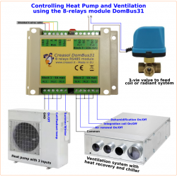
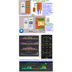
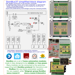
Home automation system controlling a heat pump for climate / hot water
Heat pumps may have a standby power consumption of 5W or more: they stay On for long time, but also stay Off for very long time, so it makes sense to enable heat pump power supply only when needed. The following diagram shows how to manage the heat pump by DomBus21 module, to get the following features on your home automation system:
use a cheap energy meter with pulsed output to measure the power and energy used by the heat pump
supply the heat pump only when needed (for climate, hot water, or anti-freeze protection)
enabling the 3-way valve only when needed
having your home automation system to send the climate On/Off signal to the heat pump (thermostat input)
in case that home automation system is down, permits to manually toggle On/Off the 3 relays by pushbuttons (this feature is available only with DomBus firmware, using the DCMD commands).
The energy consumption of the DomBus21 is about 15mW even with the relays On: considering the heat pump On for 66% of the time, the energy saved is about 25kWh/year compared to a system where the heat pump is always powered and using inefficient home automation relay modules!
Also, having the heat pump disconnected may prevent damages by 230V voltage fluctuations or electrostatic discharges.
Be careful with wirings: DomBus21 handles loads with max 15A (3.5kW), which could overheat or burn out if connections are not made correctly. High power connections must be monitored with an IR thermal camera to ensure they do not overheat when delivering high power.
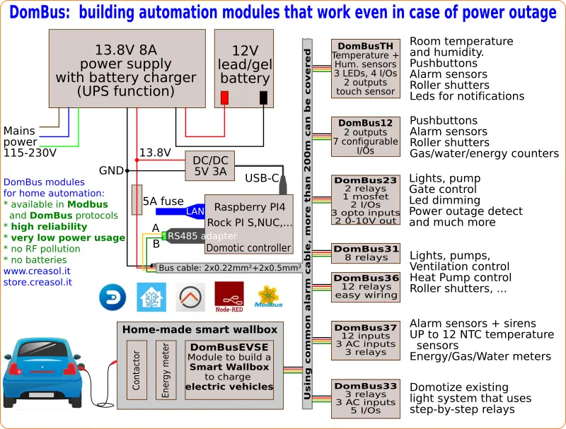
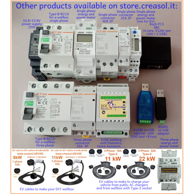
Smart-Home Creasol DomBus modules for Domoticz, Home Assistant, Node-RED, OpenHAB, ...
The following video shows a presentation of some domotic modules designed and produced in Italy by Creasol to make a reliable, easy and power-optimized home automation system.
The next video shows our Smart EVSE module that can be used to charge the electric car by using only solar power, or adding 25/50/75/100% of available power from the electrical grid.
Our industrial and home automation modules are designed to be
very low power (around 10mW with relays OFF)
reliable (no disconnections)
bus connected (no radiofrequency interference, no battery to replace).
Modules are available in two version:
with DomBus proprietary protocol, working with Domoticz only
For our products we can offer FULL SUPPORT and CUSTOMIZATION: please contact us by Email or Telegram
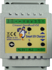
DomBusEVSE - EVSE module to build a Smart Wallbox / EV charging station
Complete solution to make a Smart EVSE, charging the electric vehicle using only energy from renewable source (photovoltaic, wind, ...), or adding 25-50-75-100% of available power from the grid.
Single-phase and three-phases, up to 36A (8kW or 22kW)
Needs external contactor, RCCB (protection) and EV cable
Optional power meter to measure charging power, energy, voltage and power factor
Optional power meter to measure the power usage from the grid (not needed if already exists)
Two max grid power thresholds can be programmed: for example, in Italy who have 6kW contractual power can drain from the grid Max (6* 1.27)=7.6kW for max 90 minutes followed by (6* 1.1)=6.6kW for another 90 minutes. The module can use ALL available power when programmed to charge at 100%.
Works without the domotic controller (stand-alone mode), and can also work with charging current set by the domotic controller (managed mode)
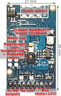
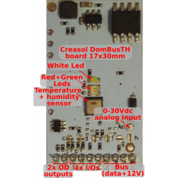
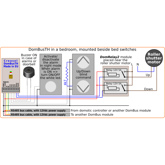
DomBusTH - Compact board to be placed on a blank cover, with temperature and humidity sensor and RGW LEDs
Compact board, 32x17mm, to be installed on blank cover with a 4mm hole in the middle, to exchange air for the relative humidity sensor. It can be installed in every room to monitor temperature and humidity, check alarm sensors, control blind motor UP/DOWN, send notifications (using red and green leds) and activate white led in case of power outage.
Includes:
temperature and relative humidity sensor
red, green and white LEDs
4 I/Os configurable as analog or digital inputs, pushbuttons, counters (water, gas, S0 energy, ...), NTC temperature and ultrasonic distance sensors
2 ports are configured by default as open-drain output and can drive up to 200mA led strip (with dimming function) or can be connected to the external module DomRelay2 to control 2 relays; they can also be configured as analog/digital inputs, pushbuttons and distance sensors.
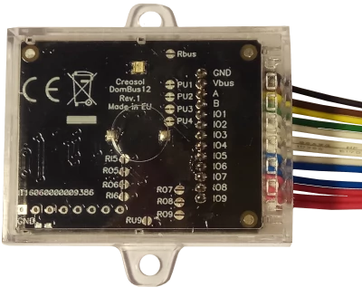
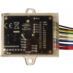
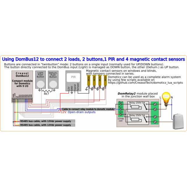
DomBus12 - Compact domotic module with 9 I/Os
Very compact, versatile and cost-effective module with 9 ports. Each port can be configured by software as:
analog/digital inputs
pushbutton and UP/DOWN pushbutton
counters (water, gas, S0 energy, ...)
NTC temperature and ultrasonic distance sensors
2 ports are configured by default as open-drain output and can drive up to 200mA led strip (with dimming function) or can be connected to the external module DomRelay2 to control 2 relays.
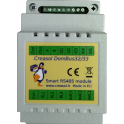
DomBus21 - Power optimized module with 3 High Power latching relays, 1 AC input and 4 low voltage inputs
Very low power consumption module designed to enable up to 3 high power loads, up to 15A (3kW).
3x high power latching relays SPST 15A: latching relay consumes nothing when ON
1x 230V AC opto-isolated input used as power outage detector, and also as zero-crossing detector to permit switching relays On/Off minimizing in-rush current (for capacitive loads) and overvoltage (for inductive loads)
4x low voltage inputs, that can be connected to pushbuttons, switches, meters with pulsed output, NTC temperature sensors, ...
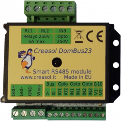
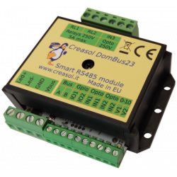
DomBus23 - Domotic module with many functions
Versatile module designed to control gate or garage door.
2x relays SPST 5A
1x 10A 30V mosfet (led stripe dimming)
2x 0-10V analog output: each one can be configured as open-drain output to control external relay
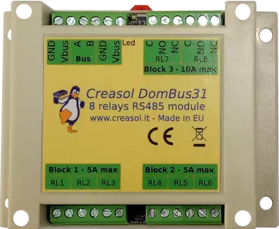
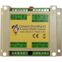
DIN rail low profile module, with 8 relays and very low power consumption:
6x relays SPST 5A
2x relays STDT 10A
Only 10mW power consumption with all relays OFF
Only 500mW power consumption with all 8 relays ON !!
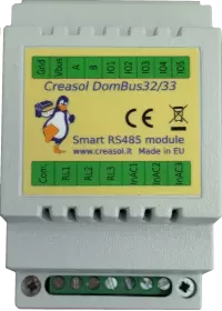
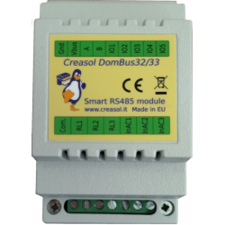
DomBus32 - Domotic module with 3 relays
Versatile module with 230V inputs and outputs, and 5 low voltage I/Os.
3x relays SPST 5A
3x 115/230Vac optoisolated inputs
Single common for relays and AC inputs
5x general purpose I/O, each one configurable as analog/digital inputs, pushbutton, counter, temperature and distance sensor.
DomBus33 - Module to domotize a light system using step relays
Module designed to control 3 lights already existing and actually controlled by 230V pushbuttons and step-by-step relays. In this way each light can be activated by existing pushbuttons, and by the domotic controller.
3x relays SPST 5A
3x 115/230Vac optoisolated inputs
Single common for relays and AC inputs
5x general purpose I/O, each one configurable as analog/digital inputs, pushbutton, counter, temperature and distance sensor.
Each relay can toggle the existing step-relay, switching the light On/Off. The optoisolator monitors the light status. The 5 I/Os can be connected to pushbuttons to activate or deactivate one or all lights.
DomBus36 - Domotic module with 12 relays
DIN rail module, low profile, with 12 relays outputs and very low power consumption.
12x relays SPST 5A
Relays are grouped in 3 blocks, with a single common per block, for easier wiring
Only 12mW power consumption with all relays OFF
Only 750mW power consumption with all 12 relays ON !!
Module designed to be connected to alarm sensors (magnetc contact sensors, PIRs, tampers): it's able to monitor mains power supply (power outage / blackout) and also have 3 relays outputs.
12x low voltage inputs (analog/digital inputs, buttons, alarm sensors, balanced double/triple biased alarm sensors, counters, temperature and distance sensors, ...)
3x 115/230Vac optoisolated inputs
2x relays SPST 5A
1x relay SPST 10A
DomBus38 - 4 SPDT 10A relays, 2 SPST 10A relays, 1 AC input, 12 low voltage inputs
DIN rail module designed for burglar alarm system.
4x relays SPDT (normally open + close contacts), 10A
2x relays SPST 10A
1x 115/230Vac optoisolated inputs, that can be used to monitor 230V voltage presence (blackout detector) and it's also used as zero-crossing detector to minimize in-rush current and overvoltage when a relay switches On/Off
12x low voltage inputs (analog/digital inputs, buttons, alarm sensors, balanced double/triple biased alarm sensors, counters, temperature and distance sensors, ...)
DomBusTracker - Smart dual-axis sun tracker to optimize photovoltaic production
DIN rail module that control azimuth + elevation/tilt motors of a sun tracker, to maximize photovoltaic energy production during the day and seasons.
Uses a deep-hole sun sensor, to optimize production with both sunny and cloudy weather
Works in stand-alone mode (no need for external controller)
Can be connected to Domoticz for monitoring and controlling the motors position
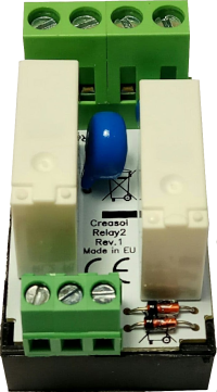
DomRelay2 - 2x relays board
Simple module with 2 relays, to be used with DomBus modules or other electronic boards with open-collector or open-drain outputs
2x 5A 12V SPST relays (Normally Open contact)
Overvoltage protection (for inductive loads, like motors)
Overcurrent protection (for capacitive laods, like AC/DC power supply, LED bulbs, ...)
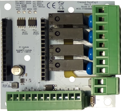
DomESP1 / DomESP2 - Board with relays and more for ESP8266 NodeMCU WiFi module
IoT board designed for NodeMCU v3 board using ESP8266 WiFi microcontroller
9-24V input voltage, with high efficiency DC/DC regulator with 5V output
4x SPST relays 5V with overvoltage protection
1x SSR output (max 40V output)
2x mosfet output (max 30V, 10A) for LED dimming or other DC loads
1x I²C interface for sensors, extended I/Os and more)
1x OneWire interface (DS18B20 or other 1wire sensors/devices)


 It uses 3 latching relays, 15A 250Vac, that does not consume anything when are active, and can be used to enable loads or generators up to 3kW that are OFF for long time. Also, removing power to loads during lightning storms helps prevent damage from electrostatic discharges.