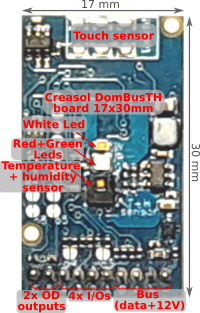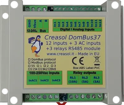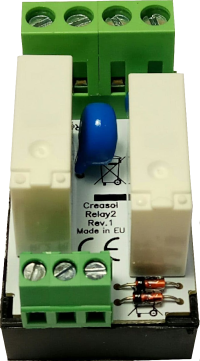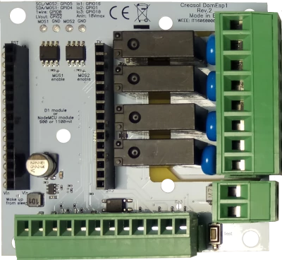
Creasol DomBusTH - zariadenie Domoticz so snímačmi teploty a vlhkosti, 4 vstupy, 2 výstupy, 3 LED
- Výpredaj!
- -30%
Email: store@creasol.it - Telegram: CreasolTech - Whatsapp: +393283730010
Prioritná pošta: rýchlo a lacno - Expresný kuriér: r
Pred vrátením produktov nás kontaktujte!
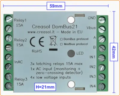
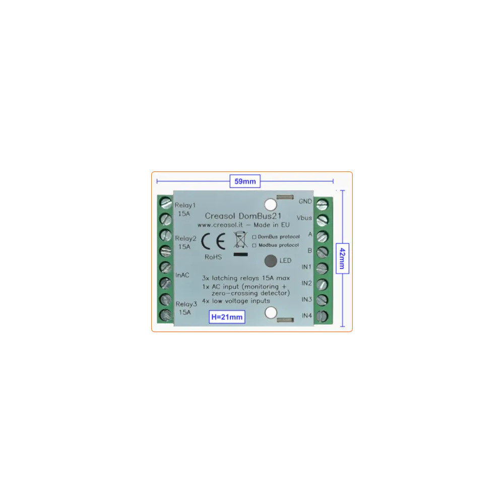
Veľmi kompaktný a nízka spotreba energie modul s 3 relé 15A, 1 AC vstup, 4 analógové/digitálne vstupy.
Email: store@creasol.it - Telegram: CreasolTech - Whatsapp: +393283730010
Prioritná pošta: rýchlo a lacno - Expresný kuriér: r
Pred vrátením produktov nás kontaktujte!
Spoľahlivý domotický modul s nízkou spotrebou energie navrhnutý tak, aby zapínal/vypínal záťaže šetriace spotrebu energie a vynuloval spotrebu v pohotovostnom režime.
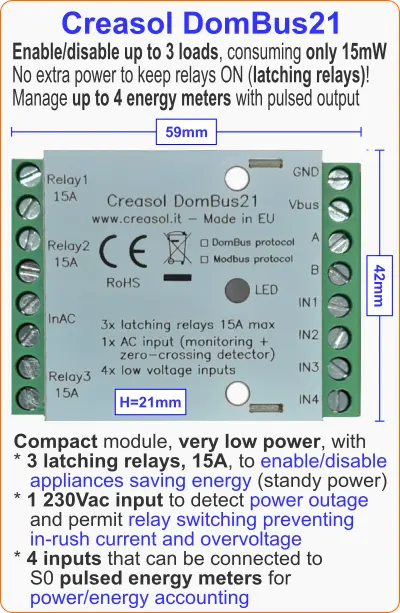
Používa sa 3 západkové relé, 15A 250Vac, ktorý nespotrebováva nič, keď je aktívny a dá sa použiť umožňujú záťaže alebo generátory až do 3 kW ktoré sú dlhodobo VYPNUTÉ. tiež odpojenie záťaže počas búrky pomáha predchádzať poškodeniu elektrostatickými výbojmi.
Má tiež 1 striedavý vstup na snímanie napätia 230 Vac (detekcia výpadku napájania), ktorý funguje aj ako detektor prechodu nulou, ktorý umožňuje aktivovať relé, keď je napätie nulové (na minimalizovať nábehový prúd v prípade kapacitných záťaží) a deaktivujte relé, keď je prúd nulový (až minimalizovať prepätie v prípade indukčnej záťaže).
4 nízkonapäťové vstupy, ktoré môžu byť nakonfigurované ako analógové alebo digitálne, umožňujú pripojenie tlačidlové spínače, NTC tepelné sondy, alarmové senzory a merače energie / plynu / vody s impulzným výstupom.
3 blokovacie relé možno použiť na aktiváciu/deaktiváciu:
Predvolená adresa: 0xff21
Port# | Meno | Schopnosti | Predvolená konfigurácia | Popis |
1 | RL1 | OUT_DIGITAL | OUT_DIGITAL | Blokovacie relé SPST 15A: cievka je aktivovaná iba počas prechodov zapnutia/vypnutia, pričom nič nespotrebováva, keď je relé zapnuté alebo vypnuté. Vstup INAC by mal byť pripojený k 230 Vac, aby sa umožnila detekcia prechodu nulou, čím sa zabráni vysokému nárazovému prúdu (pre kapacitné záťaže) a prepätiu (pre indukčné záťaže) |
2 | RL2 | OUT_DIGITAL | OUT_DIGITAL | Blokovacie relé SPST 15A: cievka je aktivovaná iba počas prechodu zap/vyp, nespotrebováva nič, keďrelé je zapnuté alebo vypnuté. Vstup INAC by mal byť pripojený k 230 Vac, aby sa umožnila detekcia prechodu nulou, čím sa zabráni vysokému nárazovému prúdu (pre kapacitné záťaže) a prepätiu (pre indukčné záťaže) |
3 | RL3 | OUT_DIGITAL | OUT_DIGITAL | Blokovacie relé SPST 15A: cievka je aktivovaná iba počas prechodov zapnutia/vypnutia, pričom nič nespotrebováva, keď je relé zapnuté alebo vypnuté. Vstup INAC by mal byť pripojený k 230 Vac, aby sa umožnila detekcia prechodu nulou, čím sa zabráni vysokému nárazovému prúdu (pre kapacitné záťaže) a prepätiu (pre indukčné záťaže) |
4 | INAC | IN_AC, IN_COUNTER | IN_AC | Optoizolovaný vstup, ktorý je možné pripojiť k ističu (na upozornenie na výpadky prúdu, špeciálne pre chladničky a tepelné čerpadlá), PIR s výstupom 230V (na monitorovanie prítomnosti), svetlu a spotrebičom (na monitorovanie zapnutia svetla alebo zariadení)./td> |
5 | IN1 | IN_DIGITAL, IN_DIGITAL_PULLDOWN, IN_ANALOG, IN_TWINBUTTON, IN_COUNTER | IN_DIGITAL | Analógový alebo digitálny vstup s voliteľným 10k pullup (prepojka PCB) a voliteľným interným pulldown (aktivovaný pri konfigurácii ako IN_DIGITAL_PULLDOWN). Spoločná svorkovnica je GND: tlačidlo, spínač, dvojtlačidlo (dvojité tlačidlo s odporom 10k medzi tlačidlami), senzor alarmu, termistor 10k NTC, počítadlo s impulzným výstupom (energetický merač, plynomer, prietokomer vody), ... treba pripojiť na tento vstup a na GND. |
6 | IN2 | IN_DIGITAL, IN_DIGITAL_PULLDOWN, IN_ANALOG, IN_TWINBUTTON, IN_COUNTER | IN_DIGITAL | Analógový alebo digitálny vstup s voliteľným 10k pullup (prepojka PCB) a voliteľným interným pulldown (aktivovaný pri konfigurácii ako IN_DIGITAL_PULLDOWN). Spoločná svorkovnica je GND: tlačidlo, spínač, dvojtlačidlo (dvojité tlačidlo s odporom 10k medzi tlačidlami), senzor alarmu, termistor 10k NTC, počítadlo s impulzným výstupom (energetický merač, plynomer, prietokomer vody), ... treba pripojiť na tento vstup a na GND. |
7 | IN3 | IN_DIGITAL, IN_DIGITAL_PULLDOWN, IN_ANALOG, IN_COUNTER | IN_DIGITAL | Analógový alebo digitálny vstup s interným pullup alebo pulldown (aktivovaný pri konfigurácii ako IN_DIGITAL_PULLDOWN). Spoločná svorkovnica je GND: na tento vstup a na GND treba pripojiť tlačidlo, spínač, alarmový senzor, počítadlo s impulzným výstupom (energetický merač, plynomer, vodomer). |
8 | IN4 | IN_DIGITAL, IN_DIGITAL_PULLDOWN, IN_ANALOG, IN_COUNTER | IN_DIGITAL | Analógový alebo digitálny vstup s interným pullup alebo pulldown (aktivovaný pri konfigurácii ako IN_DIGITAL_PULLDOWN). Spoločná svorkovnica je GND: na tento vstup a na GND treba pripojiť tlačidlo, spínač, alarmový senzor, počítadlo s impulzným výstupom (energetický merač, plynomer, vodomer). |
Pri zapnutí modul zobrazuje na červenej LED aktuálnu adresu Modbus slave (adresa registra=8192) v desiatkovom formáte, na zelenej LED sériovú prenosovú rýchlosť (reg. 8193) a nakoniec na červenej LED sériovú paritu (reg. 8194 ).
Ak je hodnota nula, vyšle sa dlhý záblesk.
napr.ak reg(8192)=33, reg(8193)=0, reg(8194)=0, pri napájaní sa zobrazia nasledujúce blikajúce LED diódy:
3 červené bliknutia, pauza, 3 červené bliknutia (podriadená adresa= 0x21 = 33 desatinných miest), pauza, 1 dlhé zelené bliknutie (reg(8193)=0 => prenosová rýchlosť=115200bps), pauza, 1 dlhé červené bliknutie (reg(8194) =0 => parita = žiadna).
Zariadenie bude funkčné iba vtedy, keď sa zobrazia parametre adresy/prenosovej rýchlosti/parity: potom modul bude akceptovať príkazy od Modbus RTU a pravidelne zobrazuje stav výstupu pre všetky porty, od 1 po max port: zelené blikanie znamená, že stav portu je vypnutý, červená blikanie znamená, že port je zapnutý.
Predvolená adresa podriadeného: 33 (0x21)
Adr | Meno | hodnoty | Popis |
0 | RL1 | 0=OFF, 1 alebo 65280=ON, 2-65279=ON na určený čas. Logiku je možné invertovať zadaním možnosti INVERTED (na adrese 512+port) |
Blokovacie relé SPST 15A: cievka je aktivovaná iba počas prechodov zapnutia/vypnutia, pričom nič nespotrebováva, keď je relé zapnuté alebo vypnuté. Vstup INAC by mal byť pripojený k 230 Vac, aby sa umožnila detekcia prechodu nulou, čím sa zabráni vysokému in-nárazový prúd (pre kapacitné záťaže) a prepätie (pre indukčné záťaže) |
1 | RL2 | 0=OFF, 1 alebo 65280=ON, 2-65279=ON na určený čas. Logiku je možné invertovať zadaním možnosti INVERTED (na adrese 512+port) |
Blokovacie relé SPST 15A: cievka je aktivovaná iba počas prechodov zapnutia/vypnutia, pričom nič nespotrebováva, keď je relé zapnuté alebo vypnuté. Vstup INAC by mal byť pripojený k 230 Vac, aby sa umožnila detekcia prechodu nulou, čím sa zabráni vysokému nárazovému prúdu (pre kapacitné záťaže) a prepätiu (pre indukčné záťaže) |
2 | RL3 | 0=OFF, 1 alebo 65280=ON, 2-65279=ON na určený čas. Logiku je možné invertovať zadaním možnosti INVERTED (na adrese 512+port) |
Blokovacie relé SPST 15A: cievka je aktivovaná iba počas prechodov zapnutia/vypnutia, pričom nič nespotrebováva, keď je relé zapnuté alebo vypnuté. Vstup INAC by mal byť pripojený na 230 Vac, aby sa umožnila detekcia prechodu nulou, čím sa zabráni vysokému nárazovému prúdu (pri kapacitných záťažiach) a prepätiu (pri indukčnej záťaži) |
3 | INAC | 0=VYPNUTÉ (plávajúce), 1=ZAPNUTÉ (rozpoznaný signál 100-250V) | Optoizolovaný vstup, ktorý je možné pripojiť k ističu (na upozornenie na výpadky prúdu, špeciálne pre chladničky a tepelné čerpadlá), PIR s výstupom 230V (na monitorovanie prítomnosti), svetlu a spotrebičom (na monitorovanie zapnutia svetla alebo zariadení)./td> |
4 | IN1 | 0=OFF, 1=ON alebo 0-65535, ak je port nakonfigurovaný ako analógový. Viac informácií nájdete nižšie. |
Analógový alebo digitálny vstup s voliteľným 10k pullup (prepojka PCB) a voliteľným interným pulldown (aktivovaný pri konfigurácii ako IN_DIGITAL_PULLDOWN). Spoločná svorkovnica je GND: tlačidlo, spínač, dvojtlačidlo (dvojité tlačidlo s odporom 10k medzi tlačidlami), senzor alarmu, termistor 10k NTC, počítadlo s impulzným výstupom (energetický merač, plynomer, prietokomer vody), ... treba pripojiť na tento vstup a na GND. |
5 | IN2 | 0=OFF, 1=ON alebo 0-65535, ak je port nakonfigurovaný ako analógový. Viac informácií nájdete nižšie. |
Analógový alebo digitálny vstup, s voliteľným 10k pullup (prepojka PCB)a voliteľný interný rozbaľovací zoznam (aktivovaný pri konfigurácii ako IN_DIGITAL_PULLDOWN). Spoločná svorkovnica je GND: tlačidlo, spínač, dvojtlačidlo (dvojité tlačidlo s odporom 10k medzi tlačidlami), senzor alarmu, termistor 10k NTC, počítadlo s impulzným výstupom (energetický merač, plynomer, prietokomer vody), ... treba pripojiť na tento vstup a na GND. |
6 | IN3 | 0=OFF, 1=ON alebo 0-65535, ak je port nakonfigurovaný ako analógový. Viac informácií nájdete nižšie. |
Analógový alebo digitálny vstup s interným pullup alebo pulldown (aktivovaný pri konfigurácii ako IN_DIGITAL_PULLDOWN). Spoločná svorkovnica je GND: na tento vstup a na GND treba pripojiť tlačidlo, spínač, alarmový senzor, počítadlo s impulzným výstupom (energetický merač, plynomer, vodomer). |
7 | IN4 | 0=OFF, 1=ON alebo 0-65535, ak je port nakonfigurovaný ako analógový. Viac informácií nájdete nižšie. |
Analógový alebo digitálny vstup s interným pullup alebo pulldown (aktivovaný pri konfigurácii ako IN_DIGITAL_PULDOWN). Spoločnou svorkovnicou je GND: tlačidlo, spínač, snímač alarmu, počítadlo s impulzomvýstup (energetický merač, plynomer, prietokomer vody), ... treba pripojiť na tento vstup a na GND. |
256-273 | Konfigurácia portu | 1=OUT_DIGITAL, 2=OUT_RELAY_LP, ... |
Príkaz používaný na konfiguráciu portu 1 (256), portu 2 (257), ... ako OUT_DIGITAL alebo OUT_RELAY_LP (relé s nízkou spotrebou energie) alebo inej hodnoty (pozri tabuľku nižšie) |
512-529 | Možnosť portu | 0 = NORMÁLNE, 1=INVERTOVANÝ (výstup normálne ZAPNUTÝ alebo vstup je ZAPNUTÝ, keď je napätie portu 0V) | Nastavte možnosť portu. Ak je nastavená na 1, výstup zostane zapnutý po zavedení, kým sa port nepotvrdí (potom sa relé vypnú). Pre vstupy, pri nastavení INVERTED, je hodnota portu ON (1), keď je vstupné napätie 0 V, OFF, keď je vstup otvorený s interným pullhigh povoleným. |
8192 | Adresa otroka | 1-247 | Umožňuje zmeniť podriadenú adresu modulu, takže je možné k nemu pridať ďalšie modulyrovnaký autobus |
8193 | Sériová bitová rýchlosť | 0 = 115 200 bps, 1=57600, 2=38400, 3=19200, 4=9600, 5=4800, 6=2400, 7=1200 bps | Sériová rýchlosť, predvolená 115200 bps 8,n,1 |
8194 | Sériová parita | 0 = Žiadne, 1 = párne, 2 = nepárne | Sériová parita, predvolená žiadna (115200 bps 8,n,1) |
8198 | Revízia, major | Iba na čítanie | Získajte verziu firmvéru, hlavné číslo. Napríklad „02“ znamená, že revízia je „02XX“, kde XX je definované parametrom 8199 |
8199 | Revízia, drobná | Iba na čítanie | Získajte verziu firmvéru, menšie číslo. Napríklad "h1" znamená, že revízia je "XXh1", kde XX je definované parametrom 8198 |
Je možné aktivovať jeden alebo viac výstupov prera určitý čas (monostabilný/výstup časovača), ako je uvedené v tabuľke. Parameter zodpovedajúci potrebnému času možno vypočítať pomocou nasledujúcich pravidiel:
Od 0 do 60 s => 31,25 ms rozlíšenie 2 = 62,5 ms, 3 = 93,75 ms, ... 1920 = 60 s => hodnota = čas_v_milisekundách/31,5
Od 1m do 1h s rozlíšením 1s 1921=61s, 3540+1920=5460=1h => hodnota=(čas_v_sekundách-60)+1920
Od 1h do 1d s rozlíšením 1m 5461=1h+1m, 1380+5460=6840=24h => hodnota=(time_in_minutes-60)+5460
Od 1d do 1500 dní s 1h rozlíšením 6841=25h, 6842=26h a tak ďalej => hodnota=(čas_v_hodinách-24)+6840
Nasledujúce tabuľky zobrazujú niektoré príklady príkazov Modbus.
Slave Addr | Func. kód | Reg.Addr | Reg.Hodnota | Rám | Popis |
55 | 06 | 8192 | 1 | [37][06][20][00][00][01][xx][xx] | Zmeňte adresu podriadeného z 54 (0x36) na 1 |
01 | 06 | 8193 | 4 | [01][06][20][01][00][04][D2][09] | Nastavte sériovú rýchlosť na 9600 bps |
01 | 06 | 8194 | 1 | [01][06][20][02][00][01][E2][0A] | Nastavte párnu paritu |
49 | 10 | 8192 | 1,4,1 | [31][10][20][00][00][03][06][00][01][00][04][00][01][B1][71] | Jediným príkazom,nastavte adresu slave na 1, sériovú rýchlosť na 9600bps, párnu paritu. Pôvodná adresa modulov bola v tomto príklade 49 (0x31). |
01 | 06 | 0 | 65280 | [01][06][00][00][FF][00][C8][3A] | Aktivovať výstup RL1 navždy (65280=0xff00) |
01 | 06 | 1 | 960 | [01][06][00][01][03][C0][D8][AA] | Aktivujte RL2 na 960/32=30s |
01 | 06 | 255 | 0 | [01][06][00][FF][00][00][B9][FA] | Zakázať všetky výstupy (Reg.Addr=255) |
01 | 10 | 0 | 32,0,0,65280 | [31][10][00][00][00][04][08][00][20][00][00][00][00][FF][00][E6][5C ] | Nastavte RL1 On na 1s (32), RL2 Off, RL3 Off, RL4 On - jedným príkazom je možné nastaviť max 10 registrov |
01 | 03 | 255 | 1 | [01][03][00][FF][00][01][B4][3A] | Prečítajte si 16bitovú hodnotu so stavom portov. Ak je napríklad vrátená hodnota 0xd1 (0b11010001), stav výstupu je: RL8=Zapnuté, RL7=Zapnuté, RL6=Vypnuté, RL5=Zapnuté, RL4=Vypnuté, RL3=Vypnuté, RL2=Vypnuté, RL1=Zapnuté |
01 | 03 | 8198 | 2 | [01][03][20][06][00][02][2F][CA] | Čítajte 4 bajty v rámci verzie modulu. Napríklad, ak je vrátená hodnota <30><32><68><31> (v hexadecimálnom formáte), zodpovedajúca hodnota ASCII je "02h1" (Firmvér 02h1) |
01 | 0F | 0 | 8,1,0xd1 | [01][0F][00][00][00][08][01][D1][3E][C9] | Nastavte stav cievky na 0xd1 (0b11010001), aktivujte RL8, RL7, RL5, RL1 a vypnite ostatné relé |
01 | 01 | 0 | 8 | [01][01][00][00][00][08][3D][CC] | Prečítajte si stav cievky. Ak je vrátená hodnota 0xd1 (0b11010001), znamená to, že RL8, RL7, RL5 a RL1 sú zapnuté |
Protokol Modbus je možné jednoducho otestovať pomocou programu modbus, napr mbpoll pre Linux:
mbpoll -v -m rtu -0 -1 -a1 -b115200 -Pžiadny -r 0 /dev/ttyUSB0 32 0 64 128 0 0 0 65280
na aktiváciu RL1 na 1s, R3 na 2s, RL4 na 4s a RL8 navždy.
mbpoll -v -m rtu -0 -1 -a1 -b115200 -Pžiadny -r 255 -c 1 /dev/ttyUSB0
na čítanie všetkých stavov prístavov.
Tepelné čerpadlá môžu mať spotrebu energie v pohotovostnom režime 5 W alebo viac: zostávajú zapnuté po dlhú dobu, ale tiež zostávajú veľmi dlho vypnuté, takže má zmysel povoliť napájanie tepelného čerpadla iba v prípade potreby.
Nasledujúci diagram ukazuje, ako spravovať tepelné čerpadlo pomocou modulu DomBus21, aby ste získali nasledujúce funkcie vo vašom systéme domácej automatizácie:
Spotreba energie DomBus21 je približne 15 mW aj so zapnutými relé: vzhľadom na to, že tepelné čerpadlo je zapnuté na 66 % času, ušetrená energia je približne 25 kWh/rok v porovnaní so systémom, kde je tepelné čerpadlo vždy napájané a využíva neefektívne reléové moduly domácej automatizácie!
tiež odpojením tepelného čerpadla môžete zabrániť poškodeniu kolísaním napätia 230 V alebo elektrostatickými výbojmi.
Buďte opatrní s kabelážou: DomBus21 zvláda záťaže s max. 15A (3,5kW), ktoré by sa mohli prehriať alebo vyhorieť, ak nie sú pripojenia vykonané správne. Vysokovýkonné pripojenia musia byť monitorované IR termokamerou, aby sa zabezpečilo, že sa pri dodávaní vysokého výkonu neprehrievajú.
Modbus address | Modbus value | DomBus parameter | Function |
---|---|---|---|
8192 | 1-247 | HWADDR=0xNNNN | This command sets a new address for the DomBus module. Be sure to assign to each module a unique address, to avoid conflicting modules. DomBus protocol and Domoticz: choose a device associated to the module, edit and add in the description field the text ,HWADDR=0x0001 for example, to assign address 1 to the module. Reload the Switches panel to see the new devices associated to the new module address. NNNN must be a number in exadecimal format, from 0x0001 to 0xff00, so 65280 combinations are available. Keep note of address assegnated to each dombus device, because in case of conflicting addresses it's needed to switch off one of the conflicting device and program the remaining one to another address, or make a factory reset as explained below. Domoticz example: ID=ff23.1,OUT_RELAY_LP,HWADDR=0x2301 to change address from ff23 to 2301 Modbus example using the program mbpoll: mbpoll -v -b115200 -Pnone -mrtu -a227 -0 -1 -r8192 /dev/ttyUSB0 12 to change address from 227 to 12 |
8193 | 0-7 | Not available | Set the serial bitrate to: 0 → 115200 bps (default) 1 → 57600 bps 2 → 38400 bps 3 → 19200 bps 4 → 9600 bps 5 → 4800 bps 6 → 2400 bps 7 → 1200 bps Modbus example using the program mbpoll: mbpoll -v -b115200 -Pnone -mrtu -a227 -0 -1 -r8193 /dev/ttyUSB0 4 to change bitrate from 115200 to 9600bps |
8194 | 0-2 | Not available | Set the serial parity to: 0 → none (default) 1 → even 2 → odd Modbus example using the program mbpoll: mbpoll -v -b115200 -Pnone -mrtu -a227 -0 -1 -r8194 /dev/ttyUSB0 1 to change parity from none to even |
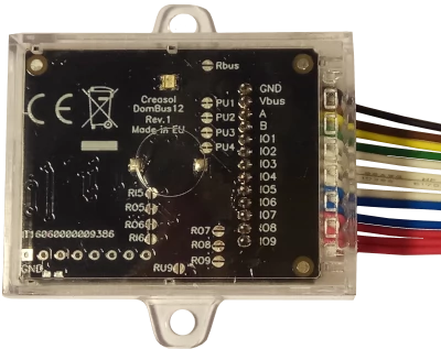
512+Port#-1 | 0 | NORMAL | Used the standard logic state for an input or output: for a digital input, On correspond to high voltage (normally 3.3V) and Off with low voltage (input shorted to GND); for an output, On corresponds to relay or open-drain mosfet active, while Off corresponds to relay/mosfet disabled. Can be used inverted with the INVERTED option (below). Domoticz example: ID=2301.1,OUT_RELAY_LP,NORMAL to get relay active when ON, and deasserted when OFF (normal behaviour). To invert, write INVERTED instead of NORMAL. |
512+Port#-1 | 1 | INVERTED | Used to invert the logic state of an input or output. Can be used in conjuction with OUT_DIGITAL, OUT_RELAY_LP, IN_DIGITAL, DIMMER. For digital inputs, On corresponds with input shorted to GND, while Off corresponds to input open (with internal pullup to 3V3). For outputs, On means that relay/mosfet output is OFF and OFF means that relay/mosfet output is ON. Domoticz example: ID=2301.1,OUT_RELAY_LP,INVERTED to get relay normally active (when domoticz device is Off). To negate this condition, write NORMAL instead of INVERTED. |
512+Port#-1 | 2 | PULLUP | Used to force the microcontroller internal pullup. Domoticz example: ID=2301.6,IN_DIGITAL,PULLUP to have the pullup active on port 6 (default behaviour) |
512+Port#-1 | 4 | PULLDOWN | Used to force the microcontroller internal pulldown. Can be used on inputs that should be normally at logic level 0, and should go to level 1 when a positive voltage is applied to the port. Domoticz example: ID=2301.6,IN_DIGITAL,PULLDOWN to have the internal pulldown active on port 6. To restore to the default behaviour, write PULLUP instead of PULLDOWN. |
256+Port#-1 | 1 | OUT_DIGITAL | Digital output, open-drain or relay output. For this kind of port it's possible to set the port value to 0 → OFF 1 or 0xff00 → ON forever From 2 to 1920 → N*31.25ms (1920=60s) From 1921 (61s) to 3540 (3600s=1h) → 1s resolution From 5461 (61m), 6840 (1440m=24h) → 1m resolution From 6841 (25h) to 65535 → 1h resolution Domoticz example: ID=2301.1,OUT_DIGITAL to configure the port 1 as a digital output |
256+Port#-1 | 2 | OUT_RELAY_LP | Can be used with relay outputs and open-drain outputs connected to relay coil, to reduce power consumption As for OUT_DIGITAL mode, it's possible to specify a port value to get OFF and ON state, and ON including a timeout (monostable) Domoticz example: ID=2301.1,OUT_RELAY_LP to configure the port 1 as a relay output optimized for low power consumption. |
256+Port#-1 | 4 | OUT_DIMMER | Set the output as DIMMER, from 0 to 100% using 5% step, 500Hz frequency. Suitable to control LED strip lights Domoticz example: ID=2301.7,OUT_DIMMER to configure IO7 as output with dimmer function. |
256+Port#-1 | 5 | OUT_BUZZER or OUT_FLASH (same behaviour) | In case the port supports OUT_BUZZER mode, it's possible to connect a piezo buzzer (without the oscillator inside!!) between this port and the next one (push-pull, 3.3V, 6.6V peak-to-peak) to get a 5KHz signal on buzzer. In case the port does not support OUT_BUZZER mode (Led, I/O, open-drain or relay output), the I/O can be used to supply a LED or a blinker. The Domoticz switch should be configured as Selector Switch: in this case the port will output 1 more short alerts to notify a status, followed by a 2s pause. Using Modbus version, the Port#-1 register value can be set to: 0 → buzzer/led/blinker OFF 1 → buzzer/led/blinker ON 2 → buzzer/led/blinker ON for 250ms 3 → buzzer/led/blinker ON for 500ms 4 → buzzer/led/blinker ON for 750ms ... 9 → buzzer/led/blinker ON for 2s 10 → 1 beep/flash, then 2s pause, forever 11 → 1 beep/flash, 2s pause, then OFF 12 → 1 beep/flash, 2s pause, for 2 times 13 → 1 beep/flash, 2s pause, for 3 times ... 19 → 1 beep/flash, 2s pause, for 9 times 20 → 2 beeps/flash, 2s pause, forever 21 → 2 beeps/flash, 2s pause, then OFF and so on... The same behaviour when using DCMD command to control a buzzer/led/blinker output. Please note that some I/O may need to have the INVERTED option set, to work as expected. Domoticz example: ID=2301.6,OUT_FLASH to configure port as Led/Buzzer sending pulses to notify a status. |
256+Port#-1 | 24 | OUT_BLIND |
Port configured to control a blind, in close direction. Next port will be automatically configured as blind in open direction. Ports OUT1 and OUT2 can directly be connected to 12V relay coils (if Vbus is 12-14V, or 24V relay coils if Vbus is 24V). Ports IN1..IN3 can be configured as OUT_BLIND, but in this case should be connected to relayboard that already have a transitors/optocouplers to drive relays. Domoticz example: ID=2301.1,OUT_BLIND to configure output as Motor DOWN/UP (next port will be used to supply the UP coil of the motor). |
256+Port#-1 | 3 | OUT_LEDSTATUS | Configure a LED port to show the device status (flashes when a frame is transmit to the RS485 bus) Domoticz example: ID=5101.a,OUT_LEDSTATUS to configure port 10 (0x0a in hex correspond to 10 in decimal) as LED status which flashes when a frame is transmitted. |
256+Port#-1 | 25 | OUT_ANALOG | Set output as analog, with 0-10V linear output. It can be used to control another electronic board with 0-10V or 1-10V input (light dimmer, heat pump power, linear valve, ....). The domotic controller will display a device with a slider, like dimmer, with values from 0 (=0V) to 100 (=10V). Using Domoticz, it's possible to create LUA or dzEvent automations that automatically change the output voltage according to some inputs (brightness, temperature, renewable power availability, ...): the DAC value can be set using the syntax commandArray['DEVICE_NAME']='Set Level 74'
to set the output voltage to 7.4V.Domoticz example: ID=2301.4,OUT_ANALOG to configure port as 0-10V analog output |
256+Port#-1 | 7 | IN_DIGITAL | Digital input, is On when the corresponding input is at high voltage level (open), and Off when the corresponding input is at GND (shorted). To inverted the logic (On when input is shorted to GND and Off when it's open) set the INVERTED option. Domoticz example: ID=2301.6,IN_DIGITAL,INVERTED to configure port 6 as digital input, inverted logig so the logic status is ON when port voltage is 0V and OFF when port voltage is high. |
256+Port#-1 | 11 | IN_DIGITAL_PULLDOWN | Digital input with microcontroller pulldown enabled: if no external pullup are enabled, the input is normally at 0V (logic 0) and goes to logic 1 when a positive voltage is applied (up to 30V for DomBus37, but should be no more than 5V with other modules). It's possible to invert the logic by setting the INVERTED option. Domoticz example: ID=3701.12,IN_DIGITAL_PULLDOWN to configure port 12 as digital input, ON when a positive voltage is applied to the port. |
256+Port#-1 | 6 | IN_AC | Optoisolated input, used to monitor the presence of the AC voltage (100-250Vac). Return 1 in case that voltage is applied, 0 if no voltage is applied to the AC input. It's possible to invert the logic by setting the INVERTED option. Dombus modules that have at least one IN_AC input, since 2024-09-24 the first AC input (INAC or INAC1 port) is used also as a zero-crossing detector to switch ON/OFF relays minimizing the in-rush current (when enabling power to capacitive loads) and overvoltage (when disabling power to inductive loads). Domoticz example: ID=3701.13,IN_AC to configure port 13 as digital input, ON when AC voltage is applied, OFF when no voltage is applied (power outage?). |
256+Port#-1 | 8 | IN_ANALOG | Port configured as IN_ANALOG can be used to measure DC voltage, like battery voltage, bus voltage, thermistors and temperature sensors, .... The voltage is sampled every 15 seconds. On DomBusTH, one or more of the 4 input wires can be configured as analog inputs, 0-3V range, but please note that an internal 10k pullup resistor is connected to each input. Also, external resistive divider should be added to measure higher voltages, so the voltage at the input terminal block must be less or equal than 3.3V. On DomBus12 it's possible to use IO7, IO8 and IO9 ports as analog inputs. Also, it's possible to use IO1, IO2, IO3, IO4 ports as analog inputs, but in this case it's needed to open, using a cutter, the corresponding PCB jumper PU1-PU4 (that internally connect the input line with a 10k pullup resistor): for example, to use IO1 as analog input, the PU1 PCB jumper must be open. Analog voltage must not exceed the 0-3V range: if voltage range is higher, a resistive divider must be applied externally. On DomBus23 only IO1 and IO2 ports can be configured as analog inputs: only 0-3V range is supported, and a resistive divider must be externally connected to measure higher voltages. Other DomBus modules have ANALOG inputs: check the specification on the product page. Domoticz example: ID=2301.6,IN_ANALOG,A=0.000611393 to set port as analog input (with output value in the range 0-65535 corrisponding to 0V-3.3V) with the linear conversion using the specified A coefficient. |
256+Port#-1 | 9 | IN_TWINBUTTON | This is a method to connect two pushbuttons/switches to a single input, to get a UP/DOWN/STOP select switch. The two switches are connected together by a 10kOhm resistor, using the schema indicated in the application notes below. Ports on DomBus module must have an internal 10k pullup (always enabled, or enabled by a PCB jumper), and output value are: 0 → OFF (buttons not pushed) 10 → DOWN button 20 → UP button Domoticz example: ID=2301.6,IN_TWINBUTTON to configure the port as double pushbutton switch OFF/DOWN/UP. |
IN_COUNTER | Used to count pulses, max 16 pulses/second (57kW max using 1000pulses/kWh meter, or 28kW max using 2000pulses/kWh meter). This solution is perfect to count energy, gas, water, ...If TYPENAME=kWh is also specified in Description, a device with both energy and power will be created. Other options that can be set for this kind of device is OPPOSITE=dev to set the device counting energy in the opposite direction (import vs export), and DIVIDER=nnnn where nnnn is the number of pulses/kWh (default 1000, but can be 1666, 2000 or any reasonable value). Domoticz example: ID=2301.6,IN_COUNTER,typename=kWh,DIVIDER=1666,OPPOSITE=99 to configure the port as a energy meter (kWh), incremented every time one or more pulses are received; it goes to 0W when device with Unit=99 send one or more pulses. |
||
256+Port#-1 | 13 | DISTANCE | Used to connect the port to a ultrasonic distance sensor like JSN-SR04T, to get the distance in millimeters. DomBus modules support more than one distance sensor, with the trigger inputs connected together to a specific port. Each module has an echo output that should be connected to an input port of the module: 1 port for each module. Both trigger and echo ports should be configured as DISTANCE. Domoticz example: ID=1202.1,DISTANCE to configure the port as DISTANCE sensor. More information in the application notes and FAQ. |
A | For analog and distance sensors: used to compute the real value using the formula REAL_VALUE=A * VALUE_FROM_DOMBUS + B. Domoticz example: ID=2301.6,IN_ANALOG,A=0.00123,B=-10 to set port as analog input, and get an output value as 0.00123*VALUE-10 where VALUE=0-65535 corresponding to 0V-3.3V. |
||
B | For analog and distance sensors: used to compute the real value using the formula REAL_VALUE=A * VALUE_FROM_DOMBUS + B For temperature, used to calibrate the value using the formula REAL_TEMPERATURE=MEASURED_TEMPERATURE + B Domoticz example: ID=0101.3,DISTANCE,A=-0.1,B=165 to set the analog/distance port to get an output value computed as 165-0.1*VALUE. |
||
CAL | Used to calibrate the temperature and relative humidity sensors inside the DomBusTH module CAL=0 remove any calibration value. CAL=0.2 increase the temperature or humidity value by 0.2. CAL=-0.2 reduce the temperature and humidity value by 0.2 The calibration value is stored into non-volatile memory. Domoticz example: ID=5101.b,HUMIDITY,CAL=-2 to calibrate the sensor to get outputValue=measuredValue-2 |
||
FUNCTION | For analog input with internal 10k pullup (I/Os that can be configured as IN_TWINBUTTON) connected to a NTC thermistor, to convert the read analog value to a temperature. Supported types: FUNCTION=3950 for NTC with Bcoeff=3950 Example: IN_ANALOG,FUNCTION=3950,B=-0.3 to use 3950 type NTC 10k@25°C, and calibrate offset -0.3°C. First configure device as IN_ANALOG and then as IN_ANALOG,FUNCTION=3950 As FUNCTION parameter enable a conversion performed by the domotic controller (not inside the DomBus module), DCMD(Value:min:max) command can be added but min and max value should be the analog values in the range 0 (corresponding to input at 0V) and 65535 (corresponding to 3.3V) Domoticz example: ID=2301.6,IN_ANALOG,FUNCTION=3950 to set port as a NTC temperature sensor. |
||
DIVIDER | Used with IN_COUNTER ports to set how many pulses per unit of measure. For example, using energy meter with 2000 pulses/kWh, the option DIVIDER=2000 should be set; in case of water meter with 20000 pulses/m³, DIVIDER=20000 should be set. Domoticz example: ID=2301.6,IN_COUNTER,DIVIDER=1000 to get outputValue incremented every 1000 pulses. |
||
TYPENAME | Option to force the creation of a the specified Domoticz. For example, IN_COUNTER,TYPENAME=kWh to create a energy/power meter instead of a normal incremental counter, or IN_ANALOG,TYPENAME=Temperature,A=0.123,B=-50 to get an analog input that return a temperature using the linear equation Temperature=A*x+B where x is the analog value read Domoticz example: ID=2301.6,IN_COUNTER,TYPENAME=kWh to create a device type kWh. |
||
OPPOSITE | Used for kWh devices, measuring electric power and energy. Suppose to have a PowerMeter Import device, with Unit=98 (see Setup → Devices), measuring the power/energy from grid, and PowerMeter Export, with Unit=99, measuring the power/energy produced and fed to the grid. If these devices are connected to the pulse output of an energy meter, when a pulse is received from the Import device it means that exported power is 0, and vice-versa. This parameter is used to set what is the Unit number associated to the opposite counter. So, PowerMeter Import description must have IN_COUNTER,TYPENAME=kWh,OPPOSITE=99 and PowerMeter Export description IN_COUNTER,TYPENAME=kWh,OPPOSITE=98 Domoticz example: ID=2301.6,IN_COUNTER,TYPENAME=kWh,OPPOSITE=123 to get a energy meter with power goes to 0W when device with Unit=123 transmits a pulse. |
||
ADDR | EVSE: used to set the Modbus address of a DDS238-2 ZN/S (or DTS238-x ZN/S) energy meter. By default DDS238 has address=1 and baud rate 9600. Setting ADDR=2 to set the Modbus to the specified value. On DomBusEVSE module, address 2 is used to measure charging power/energy, and address 3 to measure grid power/energy. Valid range from 2 to 5. This parameter can be set only for the M1 Addr and Power Factor devices (EV PF, M3 PF, M4 PF, M5 PF) to change the Modbus address of energy meters that have address in the 1-5 range to another value) Domoticz example: ID=ffe3.d,CUSTOM,TypeName=Text,ADDR=2 to set Modbus address of the energy meter to 2 In case you want to change the Modbus slave address manually, it's a little complicated because DDS238 / DTS238 use the function code 0x10 to change a single register, so it cannot be done by mbpoll software. Below some example: echo -en '\x04\x10\x00\x15\x00\x01\x02\x02\x01\x5b\x65' >/dev/ttyUSB0 to change from address=4 to address=2 where the first byte corresponds to the current slave address, the 5st byte to the new slave address, and the last two bytes are the Modbus 16bit CRC (frame integrity check) calculated by writing the first 6 hex bytes to a Modbus CRC calculator, click on AnalyzeDataHex and check the CRC-16 (Modbus) Big Endian field. |
||
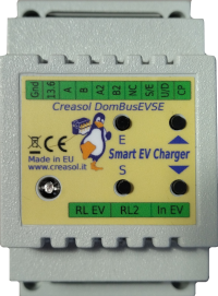
EVMAXCURRENT | EVSE: set the max charging current, that normally is limited by the cable used to connect the vehicle to the charging station. Valid range from 6 to 36, default value is 16 Ampere. This parameter can be set only for the device named EV Mode Domoticz example: ID=e301.4,EVMAXCURRENT=32 to set the max current (limited by EV cable and wirings) |
||
EVMAXPOWER | EVSE: maximum power that can be drained from the grid without any time limit (available power). Valid range from 1000 to 25000, default value 3300 Watt. This parameter can be set only for the device named EV Mode Domoticz example: ID=e301.4,EVMAXCURRENT=32,EVMAXPOWER=6600 to set the max contractual power from grid. |
||
EVMAXPOWER2 | EVSE: the highest power that can be drained from the grid, but only for a limited time. Valid range from 1000 to 25000, default value 0 (disabled). This parameter can be set only for the device named EV Mode Domoticz example: ID=e301.4,EVMAXCURRENT=32,EVMAXPOWER=6600,EVMAXPOWER2=7620 to set the absolutely max power that must never be exceeded. |
||
EVMAXPOWERTIME | EVSE: time in second to charge the electric vehicle using EVMAXPOWER Watt from grid, before increasing power to EVMAXPOWER2. Valid range from 60 to 43200 seconds, default value 0 (disabled). This parameter can be set only for the device named EV Mode Domoticz example: ID=e301.4,EVMAXCURRENT=32,EVMAXPOWER=6600,EVMAXPOWER2=7620,EVMAXPOWERTIME=1800,EVMAXPOWERTIME2=1800 to set time that EVSE module can keep the MAXPOWER and MAXPOWER2 |
||
EVMAXPOWERTIME2 | EVSE: time in second to charge the electric vehicle using EVMAXPOWER2 Watt from grid, before decreasing power to EVMAXPOWER. Valid range from 60 to 43200 seconds, default value 0 (disabled). This parameter can be set only for the device named EV Mode Domoticz example: ID=e301.4,EVMAXCURRENT=32,EVMAXPOWER=6600,EVMAXPOWER2=7620,EVMAXPOWERTIME=1800,EVMAXPOWERTIME2=1800 to set time that EVSE module can keep the MAXPOWER and MAXPOWER2 |
||
EVSTARTPOWER | EVSE: minimum available power to start charging: the minimum current is 6A, but usually the On-Board Charger charges less current than what is set, so maybe 900W is sufficient. Please note that charging at a low current lead to a poor efficiency (e.g. 30% power loss). Valid range above 800, default value 1200 Watt. This parameter can be set only for the device named EV Mode Domoticz example: ID=e301.4,EVMAXCURRENT=32,EVMAXPOWER=6600,EVSTARTPOWER=1500 to start charging only when at least 1500W are available |
||
EVSTOPTIME | EVSE: time in seconds after which the charging process is stopped if the available power is less than what is drained by the car with the minimum current (6A). This parameter is used to prevent that, expecially in SOLAR mode, the charging is ended if no power is available for a short time. Valid range from 5 to 600, default is 90 seconds. Time is internally reduced /5 in case that imported power from grid exceed the MAXPOWER parameter, to prevent disconnections. This parameter can be set only for the device named EV Mode Domoticz example: ID=e301.4,EVMAXCURRENT=32,EVMAXPOWER=6600,EVSTARTPOWER=1500,EVSTOPTIME=150 to stop charging after 150s with no enough power available. |
||
EVAUTOSTART | EVSE: can be set to 0 or 1. 0 means that this function is disabled. 1 means that this function is enabled, and permit to restart automatically the last charging mode when the vehicle is plugged again to the wallbox. Default value is 1. This parameter can be set only for the device named EV Mode Domoticz example: ID=e301.4,EVMAXCURRENT=32,EVMAXPOWER=6600,EVSTARTPOWER=1500,EVSTOPTIME=150,EVAUTOSTART=1 to start charging automatically when the vehicle is plugged. |
||
EVWAITTIME | EVSE: time to wait, in seconds, before updating the EV charge current again. By default this time is set in 7 seconds, because the SAE J1772 and IEC Standards state that On Board Charger have to adjust the power according to the value set by EVSE within 6 seconds. In case that an external grid power meter is used, with a long refresh time (more than 6 seconds), this parameter have to be set to the grid power refresh time + 1 or 2 seconds (to cover domotic controller delays). This parameter can be set only for the device named EV Mode Domoticz example: ID=e301.4,EVMAXCURRENT=32,EVMAXPOWER=6600,EVSTARTPOWER=1500,EVSTOPTIME=150,EVAUTOSTART=1,EVWAITTIME=12 to update charging current only after 12s since last update. | ||
EVMETERTYPE | EVSE: type of energy meter installed. 0=DDS238 ZN/S (for single phase power supply: default type). 1=DTS238 ZN/S (for three-phase power supply): set to 1 in case of three-phase power supply, even if energy meter is directly controlled by the home automation system. Domoticz example: ID=e301.4,EVMAXCURRENT=32,EVMAXPOWER=6600,EVSTARTPOWER=1500,EVSTOPTIME=150,EVAUTOSTART=1,EVWAITTIME=12,EVMETERTYPE=1 for three-phase EV charging station. |
||
DISABLE | Used to disable one or more ports: it can be usedful with large buses with more than 255 ports (devices), because Domoticz has a limit of max 255 devices for each bus. In this case it's possible to disable unused module ports by writing, in the Description of port 1, the list of disabled ports separated by colon, for example DISABLE=2:5:6:7:11 to disable ports 2,5,6,7,11:16 (11 corresponds with port .b in hex and 16 with port .10 in hex) of the current module. Port 1 can be never disabled. To enable a previosly disabled port, just edit the port 1 description for that module, removing the port from the list of DISABLE command: that port will be enabled again in 60 seconds (wait for 1 minute and reload the Domoticz panel). Domoticz example: ID=2301.1,OUT_RELAY_LP,DISABLE=8:9:10 to disable ports 8,9,10. |
||
DCMD | Dombus Command: through this keyword it's possible to set a command to send to the same or another module, when an event occurs. In this way, when an event occurs, the module send a command to a dombus module to execute an operation, and this work without the need of a Domoticz controller and without the need to configure Domoticz to manage this kind of actions. See the DCMD section below. Domoticz example: ID=e301.1,OUT_DIGITAL,DCMD(On)=3101.4:On,DCMD(Off)=3101.4:Off,DCMD(On)=0.12:On,DCMD(Off)=0.12:Off to enable a relay on DomBus module with hwaddr=3101 when charging is ON, and also enabling a scene on Domoticz during charging. |
||
DESCR | This is used in Domoticz to add a description or comment to the device. Please note that the comment cannot contain the comma character "," because commas are used to separate commands. For example the Domoticz description field of a ANALOG port can be something like: 12.7,IN_ANALOG,A=0.000553902,DESCR=description of the analog port without any comma; A is the conversion factor from 16bit value to voltage (36.3V max) |
This is an experimental function, undergoing testing and development, available on all DomBus modules, expept DomBus1
For each port it's possible to configure, through the Domoticz Description field, one or more DCMD commands.
DCMD is a command that is sent to the module itself or to another DomBus module, in response to an event, and more DCMD commands can be specified for the same event and port.
Also it's possible to send DCMD command to the domotica controller to activate, deactivate or toggle a scene/group; to get this feature please assure that:
The syntax is DCMD(Event:ValueLow:ValueHigh)=ModuleAddress.ModulePort:Command:Value
where ValueLow, ValueHigh, Value are optional parameters.
When ModuleAddress corresponds to the same module that we're editing, the command is executed locally, by the same module.
When ModuleAddress corresponds to another Dombus module, the command is sent by bus to that module. When ModuleAddress is 0, the command is sent to the controller to activate the scene/group with idx=ModulePort : please note that ModulePort should be in hex format, so if ModulePort=11 the scene/group with idx=17 will be activated.
Event | Description | Example |
---|---|---|
OFF | This even occurs when input goes OFF | DCMD(OFF)=13.1:OFF When input goes off, turns OFF also port 1 of module 13 |
ON | This even occurs when input goes ON |
DCMD(ON)=13.2:ON:90s |
PULSE | Input is pulsed ON for less than 0.5s | DCMD(Pulse)=13.3:TOGGLE When input is pulsed shortly, send command to module 13 port 3 to toggle it's output OFF->ON or vice versa |
PULSE1 | Input is pulsed ON for about 1s |
DCMD(Pulse1)=13.3:ON |
PULSE2 | Input is pulsed ON for about 2s |
DCMD(Pulse2)=13.3:OFF |
PULSE4 | Input is pulsed ON for about 4s |
DCMD(Pulse4)=13.4:ON:2h |
DIMMER | ||
VALUE | Sensor value is ≥ ValueLow and < ValueHigh Command is repeated every 30s if the comparison matches. |
DCMD(Value:0:20.5)=13.5:ON DCMD(Value:0:12.2)=31.7:ON DCMD(Value:0:100)=31.8:OFF |
Command | Description | Example |
---|---|---|
OFF | Turns output OFF. If the optional Value is specified, output will be OFF for the specified time, then returns ON | |
ON | Turns output ON. If the optional Value is specified, output will be ON for the specified time, then returns OFF | |
TOGGLE | Change state to the selected output. If the optional Value is specified, wait the specified time before toggling output | |
DIMMER |
Command | Description | Example |
---|---|---|
number | A number without any suffix should be multiplied by 31.25ms (seconds/32) | 1=31.25ms 3=93.75ms 16=500ms |
numberS | Number of seconds, from 1 to 3600 |
1s=1 second |
numberM |
Number of minutes, from 1 to 1440 | 1m=1 minute 10m=10 minutes 180m=3 hours |
numberH | Number of hours, from 1 to 43824 | 1h=1 hour 6h= 6 hours 72h=3 days |
numberD | Number of days, from 1 to 1826 |
1d=1 day |
IN_DIGITAL,INVERTED,
DCMD(Pulse)=0101.1:TOGGLE,
DCMD(Pulse1)=0101.2:ON:30m,
DCMD(Pulse2)=0101.2:OFF
IN_DIGITAL,INVERTED, DCMD(Pulse)=0.1:Toggle, DCMD(Pulse2)=0.2:On
In the description field of the temperature sensor we'll write
DCMD(Value:0:20.5)=0101.3:ON, (if temperature between 0 and 20.5°C, turns ON heater on output 3 of module 0x0101)
DCMD(Value:0:20.5)=0102.1:ON, (if temperature between 0 and 20.5°C, turns ON valve output 1 of module 0x0102)
DCMD(Value:20.8:50)=0101.3:OFF (turn OFF heater when temperature above 20.8°C)
DCMD(Value:20.8:50)=0102.1:OFF (turn OFF valve when temperature above 20.8°C)
Domoticz temperature sensor Description will be:
TEMPERATURE,
DCMD(Value:0:20.5)=0101.3:ON,
DCMD(Value:0:20.5)=0102.1:ON,
DCMD(Value:20.8:50)=0101.3:OFF,
DCMD(Value:20.8:50)=0102.1:OFF
A piezo buzzer (without oscillator) should be connected to IN3 and IN4, and IN3 should be configured as OUT_BUZZER.
Toggle ON/OFF group with idx=17 (0x11 in hex) with a short pulse, less than 0.5s: DCMD(Pulse)=0.11:Toggle
Create a short 500ms buzzer feedback...module address is 5101 and IN3 port is 5: DCMD(Pulse)=5101.5:On:2 where 2=2*250ms and can be increased up to 9*250ms. Then, specifying 10, 20, 30, and other multiple of 10, instead of emitting a short or long beep the buzzer produces N beeps. For example, if value is 20, 2 beeps are emitted, followed by 4s of pause, then other 2 beeps and so on.
Activate the scene with idx=16 (0x10 in hex) when the touch sensor is ON for 2s: DCMD(Pulse2)=0.10:On
In this case, also transmits a long buzzer alert, 1.5s: DCMD(Pulse2)=5101.5:On:6
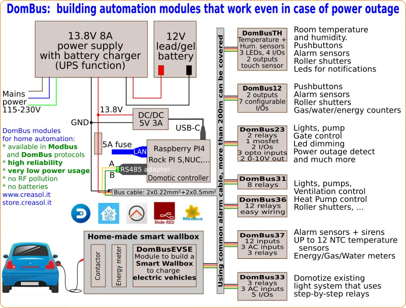
Using RS485 specific cables it's possible to get almost 1km linear bus with several devices attached. Alternatively, it's possible to use 2 twisted pairs of cheap Cat6 UTP or STP cable, one twisted pair for data (A and B) and one for 12-24V power supply. Ideally, all devices should be connected using a linear bus topology, to get the lowest reflection/noise, and connect 100-150 Ohm resistor on the two ends, as illustrated in the Fig. 2. In practice, this is not important for common buildings.
At Raspberry/PC side, it's possible to use a cheap USB-RS485 adapter, if a serial port with RS485 driver is not already available.
Using DomBus modules it's possible to:
Click here if you need to write a microSD card with a clean updated Raspbian+Domoticz image optimized to extend SD life (minimizing writings), and with some addons (firewall, backup, libraries).
This procedure is not needed in case of a new Domoticz installation writing the SD as written above.
If Domoticz does not already include the DomBus plugin, type the following commands (from Linux root shell: type sudo su - to become root):
#install git, if not already installed
which git
if [ $? -ne 0 ]; then sudo apt install git; fi
#change to the domoticz directory / plugins
cd /home/pi/domoticz/plugins
#fetch the Python Plugin Manager (that can be used to install/upgrade other plugins, including Creasol DomBus)
git clone https://github.com/ycahome/pp-manager
#fetch Creasol Plugin
git clone https://github.com/CreasolTech/CreasolDomBus
#restart Domoticz daemon
service domoticz restart
After plugins installation and Domoticz restart, it's possible to add the Creasol DomBus hardware (Setup->Hardware , add new "dombus" hardware type "Creasol DomBus" and specify the serial device, normally /dev/ttyUSB0) and connect the DomBus device to the RS485 bus.
DomBus module is factory programmed with a default address indicated above, and only one port will be automatically added to the Switches panel of Domoticz. Enter the Switches panel, find the new device with the DomBus default address, click on Edit and add in the description ,HWADDR=0x0001 to set the new address to 0001, or specify another address of your choice. Reload the Switches panel to see all input/output/led ports of DomBusTH active.
With Domoticz, each DomBus port can be configured via the Domoticz device description: for example a port IN_DIGITAL normally is On when it's left unconnected, and Off when it's shorted to GND, but it's possible to invert this function specifying in the device description the parameter INVERTED, separated by a comma (,): IN_DIGITAL,INVERTED . Relay outputs can be configured writing in the description field OUT_DIGITAL or OUT_RELAY_LP: in the latter case, relay are internally managed to assure a low power consumption.
Please check the sections Ports capabilities and Ports parameters.
Ports that are not used can be disabled in Domoticz Setup → Devices clicking on the blue arrow of each useless port (device), but in case of a bus with almost 255 ports, it's suggested to disable the unused ports by using the DISABLE command:
1. suppose that DomBus module 0x0001 has ports 3,4,5,6,8 not used
2. in Domoticz Switches panel select port1 of that module ([0001.1] RL1)
3. click on Edit, and add in the Description field DISABLE=3:4:5:6:8 and click on Save.
In this way, the selected ports will be disabled and removed from the Devices list. With this solution it's possible to add more DomBus modules to the same bus, with up to 255 enabled ports.
In large buildings, it's a good practice to have more than one bus, to divide floors or areas.
cd /tmp
git clone https://github.com/CreasolTech/home-assistant-creasol-dombus.git
cp -a home-assistant-creasol-dombus/custom_components HADIR/config/
ha core restart
where HADIR is the Home Assistant root dir: in case of Hassio, use the command cp -a home-assistant-creasol-dombus/custom_components /config/ATTRS{devpath}=="1.5" ATTRS{idProduct}=="7523" ATTRS{idVendor}=="1a86"
SUBSYSTEM=="tty", ATTRS{idVendor}=="1a86", ATTRS{idProduct}=="7523", ATTRS{devpath}=="1.5", SYMLINK+="ttyUSBdombus1"to set that the USB/RS485 adapter plugged to the USB port 1.5 should be named /dev/ttyUSBdombus1
-- script_time_example.lua : simple example script that write a message to Telegram channel/group if temperature is less than 5 commandArray={} dofile "script/lua/globalvariables.lua" -- read a file with some variables, including Telegram API key and ChatID dofile "script/lua/globalfunctions.lua" -- read a file with some functions if (tonumber(otherdevices['Temp_outdoor']) < 5) then telegramNotify("Low temperature: bring flowers inside") -- send message by Telegram end return commandArray
0 ⇒ OFF 1 ⇒ solid ON 2 ⇒ ON for 250ms 3 ⇒ ON for 500ms 4 ⇒ ON for 750ms ... 9 ⇒ ON for 2000ms 10 ⇒ 1 beep/flash followed by 2s pause, forever 11 ⇒ 1 beep/flash followed by 2s pause, only once 12 ⇒ 1 beep/flash followed by 2s pause, only twice 13 ⇒ 1 beep/flash followed by 2s pause, 3 times ... 19 ⇒ 1 beep/flash followed by 2s pause, 9 times 20 ⇒ 2 beeps/flashes followed by 2s pause, forever 21 ⇒ 2 beeps/flashes followed by 2s pause, only once 22 ⇒ 2 beeps/flashes followed by 2s pause, only twice and so on...
in Italy, if contractual power is 6kW, it's possible to drain 6kW+27% for max 90 minutes, then power must decrease below 6kW+10% for at least 90 minutes MaxPower2 (e.g. 7600 Watt) #################### ######### MaxPower (e.g. 6600 Watt) ##################################################################### ^ ^ ^ ^ Time start MaxPowerTime MaxPower2Time MaxPowerTime
Need help? join the DomBus channel on Telegram!
Esiste anche il Canale Telegram in Italiano DomBus_it!