„Creasol DomBusTH“ yra maža elektroninė plokštė, 32x17mm, pritaikyta bet kokiam tuščiam dangteliuisu 3 mm skylute centre, reikalinga šilumos / drėgmės jutikliui, norint pasikeisti oru su kambariu ir apšviesti šviesos diodus. Jį prie „Domoticz“ valdiklio galima prijungti RS485 nuosekliąja magistrale (4 laidai, 2 - 12 / 24V maitinimo šaltiniui ir 2 - duomenims esant 115200bps).
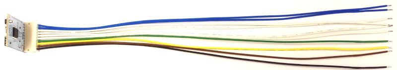
Elektroninė plokštė tiekiama su 20 cm ilgio, 10 laidų,surinkimo kabelis su įskiepio jungtimi, todėl įrenginį lengva prijungti prie mygtukų, jungiklių, relių ir kt.
Kaip ir kiti „DomBus“ įrenginiai,„DomBusTH“ sumažina energijos suvartojimą, jį automatiškai aptinka „Domoticz“, o kiekvieną prievadą galima visiškai konfigūruoti žiniatinklyje naudojant „Domoticz“ įrenginio aprašymą. Žr. Toliau, kaip pakeisti gamykloje užprogramuotą kiekvieno įrenginio adresą ir kaip „Domoticz“ žiniatinklio skydelyje sukonfigūruoti kiekvieną prievadą kaip skaitmeninius įėjimus, analoginius įėjimus, skaitmeninius išėjimus, reguliatorių, garsinį signalą, žaliuzę ir pan.
funkcijos
- temperatūros jutiklis, gamykloje sukalibruotas precisoinu +/- 0,3 ° C li>
- santykinės drėgmės jutiklis, gamykloje sukalibruotas +/- 2% RH
- 4laidai, kuriuos galima sukonfigūruoti kaipskaitmeniniai įėjimai, analoginiai įėjimai, 1mA skaitmeniniai išėjimai ir garsinis signalas:juos galima prijungti prie mygtukų, jungiklių, signalizacijos jutiklių, pjezoelektrinių garsinių signalų, ...
- 2 atvirojo kolektoriaus išėjimai su 40V 50mAgalimybė, kuri gali būti naudojama valdytiišorinės relės, elektroninių plokščių įėjimaisu prisitraukimu,maži šviesos diodai(„DomBusTH“ apimapritemdytifunkcija)
- 1 analoginis įėjimaskurie matuoja įtampą magistrale (bet gali būti sukonfigūruoti matuoti kitą išorinę įtampą, maks. 30 Vdc, lituojant papildomą laidą)
- 1 raudonas šviesos diodas, gali būti naudojamas kaip įjungtas / išjungtas arba siųsti vieną ar daugiau mirksinčių, atitinkančių įrenginio būseną
- 1 žalias šviesos diodas, gali būti naudojamas kaip įjungtas / išjungtas arba siųsti vieną ar daugiau mirksinčių, atitinkančių įrenginio būseną
- 1 baltas šviesos diodassu 700 mcd šviesos stiprumu: gali būti naudojamas kaip naktinė šviesa ir avarinė lempa arba siųsti tam tikrą būseną atitinkančių blyksčių skaičių
- 7,5-35 V DC maitinimas (viduje reguliuojamas perjungimo režimo maitinimo grandine, kuri sumažina energijos suvartojimą ir išsklaidymą)
- 115200 bps RS485 autobusas (maks. Ilgis: 1km)
Daugiau informacijos rasitehttps://www.creasol.it/CreasolDomBusTH
For any questions, suggestions, feature requests, contact us by Telegram, group DomBus.
Video showing Creasol DomBus modules in brief
DomBus modules installation block chart
Often it's important to have a
stable power to supply your Smart Home, to avoid troubles with the
domotic controller (RaspberryPI or other), have
internet connection always ON and are able to
manage alarm sensors even in case of power outage.
- Use a 12V power supply unit with backup battery charger, to avoid trouble on RaspberryPI or other devices. Also, in this way it's possible to get everything working even in case of power outage (domotic controller, domotic modules, network switches, routers, NVR and IPcams).
- Use a 12V lead-acid battery well dimensioned to supply everything during blackout.
- Use a DC/DC converter 12V → 5V 3A to supply the RaspberryPI, if you have it.
- To use DomBus modules, use a standard alarm shielded cable (within 4 wires) to interconnect all modules to RaspberryPI (through a cheap RS485 to USB adapter).
- Protect each bus with a fuse
Ports parameters
The following table shows how to configure a DomBus device by Modbus protocol or DomBus plugin/software.
The first two columns show the Modbus register address and supported values, and are applicable to the module programmed with Modbus firmware, working with Node-RED, Home Assistant, ...
The third column describe how to configure parameters from Domoticz by using the Creasol DomBus plugin, and is applicable to the module programmed with Dombus firmware (working with Domoticz).
| Modbus address |
Modbus value |
DomBus parameter |
Function |
| 8192 |
1-247 |
HWADDR=0xNNNN |
This command sets a new address for the DomBus module. Be sure to assign to each module a unique address, to avoid conflicting modules.
DomBus protocol and Domoticz: choose a device associated to the module, edit and add in the description field the text ,HWADDR=0x0001 for example, to assign address 1 to the module. Reload the Switches panel to see the new devices associated to the new module address. NNNN must be a number in exadecimal format, from 0x0001 to 0xff00, so 65280 combinations are available. Keep note of address assegnated to each dombus device, because in case of conflicting addresses it's needed to switch off one of the conflicting device and program the remaining one to another address, or make a factory reset as explained below.
Domoticz example: ID=ff23.1,OUT_RELAY_LP,HWADDR=0x2301 to change address from ff23 to 2301
Modbus example using the program mbpoll: mbpoll -v -b115200 -Pnone -mrtu -a227 -0 -1 -r8192 /dev/ttyUSB0 12 to change address from 227 to 12
|
| 8193 |
0-7 |
Not available |
Set the serial bitrate to:
0 → 115200 bps (default)
1 → 57600 bps
2 → 38400 bps
3 → 19200 bps
4 → 9600 bps
5 → 4800 bps
6 → 2400 bps
7 → 1200 bps
Modbus example using the program mbpoll: mbpoll -v -b115200 -Pnone -mrtu -a227 -0 -1 -r8193 /dev/ttyUSB0 4 to change bitrate from 115200 to 9600bps
|
| 8194 |
0-2 |
Not available |
Set the serial parity to:
0 → none (default)
1 → even
2 → odd
Modbus example using the program mbpoll: mbpoll -v -b115200 -Pnone -mrtu -a227 -0 -1 -r8194 /dev/ttyUSB0 1 to change parity from none to even
|
| 512+Port#-1 |
0 |
NORMAL |
Used the standard logic state for an input or output: for a digital input, On correspond to high voltage (normally 3.3V) and Off with low voltage (input shorted to GND); for an output, On corresponds to relay or open-drain mosfet active, while Off corresponds to relay/mosfet disabled. Can be used inverted with the INVERTED option (below).
Domoticz example: ID=2301.1,OUT_RELAY_LP,NORMAL to get relay active when ON, and deasserted when OFF (normal behaviour). To invert, write INVERTED instead of NORMAL.
|
| 512+Port#-1 |
1 |
INVERTED |
Used to invert the logic state of an input or output. Can be used in conjuction with OUT_DIGITAL, OUT_RELAY_LP, IN_DIGITAL, DIMMER.
For digital inputs, On corresponds with input shorted to GND, while Off corresponds to input open (with internal pullup to 3V3). For outputs, On means that relay/mosfet output is OFF and OFF means that relay/mosfet output is ON.
Domoticz example: ID=2301.1,OUT_RELAY_LP,INVERTED to get relay normally active (when domoticz device is Off). To negate this condition, write NORMAL instead of INVERTED.
|
| 512+Port#-1 |
2 |
PULLUP |
Used to force the microcontroller internal pullup.
Domoticz example: ID=2301.6,IN_DIGITAL,PULLUP to have the pullup active on port 6 (default behaviour)
|
| 512+Port#-1 |
4 |
PULLDOWN |
Used to force the microcontroller internal pulldown. Can be used on inputs that should be normally at logic level 0, and should go to level 1 when a positive voltage is applied to the port.
Domoticz example: ID=2301.6,IN_DIGITAL,PULLDOWN to have the internal pulldown active on port 6. To restore to the default behaviour, write PULLUP instead of PULLDOWN.
|
| 256+Port#-1 |
1 |
OUT_DIGITAL |
Digital output, open-drain or relay output. For this kind of port it's possible to set the port value to
0 → OFF
1 or 0xff00 → ON forever
From 2 to 1920 → N*31.25ms (1920=60s)
From 1921 (61s) to 3540 (3600s=1h) → 1s resolution
From 5461 (61m), 6840 (1440m=24h) → 1m resolution
From 6841 (25h) to 65535 → 1h resolution
Domoticz example: ID=2301.1,OUT_DIGITAL to configure the port 1 as a digital output
|
| 256+Port#-1 |
2 |
OUT_RELAY_LP |
Can be used with relay outputs and open-drain outputs connected to relay coil, to reduce power consumption
As for OUT_DIGITAL mode, it's possible to specify a port value to get OFF and ON state, and ON including a timeout (monostable)
Domoticz example: ID=2301.1,OUT_RELAY_LP to configure the port 1 as a relay output optimized for low power consumption.
|
| 256+Port#-1 |
4 |
OUT_DIMMER |
Set the output as DIMMER, from 0 to 100% using 5% step, 500Hz frequency. Suitable to control LED strip lights
Domoticz example: ID=2301.7,OUT_DIMMER to configure IO7 as output with dimmer function.
|
| 256+Port#-1 |
5 |
OUT_BUZZER or OUT_FLASH (same behaviour) |
In case the port supports OUT_BUZZER mode, it's possible to connect a piezo buzzer (without the oscillator inside!!) between this port and the next one (push-pull, 3.3V, 6.6V peak-to-peak) to get a 5KHz signal on buzzer. In case the port does not support OUT_BUZZER mode (Led, I/O, open-drain or relay output), the I/O can be used to supply a LED or a blinker. The Domoticz switch should be configured as Selector Switch: in this case the port will output 1 more short alerts to notify a status, followed by a 2s pause.
Using Modbus version, the Port#-1 register value can be set to:
0 → buzzer/led/blinker OFF
1 → buzzer/led/blinker ON
2 → buzzer/led/blinker ON for 250ms
3 → buzzer/led/blinker ON for 500ms
4 → buzzer/led/blinker ON for 750ms
...
9 → buzzer/led/blinker ON for 2s
10 → 1 beep/flash, then 2s pause, forever
11 → 1 beep/flash, 2s pause, then OFF
12 → 1 beep/flash, 2s pause, for 2 times
13 → 1 beep/flash, 2s pause, for 3 times
...
19 → 1 beep/flash, 2s pause, for 9 times
20 → 2 beeps/flash, 2s pause, forever
21 → 2 beeps/flash, 2s pause, then OFF
and so on... The same behaviour when using DCMD command to control a buzzer/led/blinker output.
Please note that some I/O may need to have the INVERTED option set, to work as expected.
Domoticz example: ID=2301.6,OUT_FLASH to configure port as Led/Buzzer sending pulses to notify a status.
|
| 256+Port#-1 |
24 |
OUT_BLIND |
Port configured to control a blind, in close direction. Next port will be automatically configured as blind in open direction.
Ports OUT1 and OUT2 can directly be connected to 12V relay coils (if Vbus is 12-14V, or 24V relay coils if Vbus is 24V).
Ports IN1..IN3 can be configured as OUT_BLIND, but in this case should be connected to relayboard that already have a transitors/optocouplers to drive relays.
Domoticz example: ID=2301.1,OUT_BLIND to configure output as Motor DOWN/UP (next port will be used to supply the UP coil of the motor).
|
| 256+Port#-1 |
3 |
OUT_LEDSTATUS |
Configure a LED port to show the device status (flashes when a frame is transmit to the RS485 bus)
Domoticz example: ID=5101.a,OUT_LEDSTATUS to configure port 10 (0x0a in hex correspond to 10 in decimal) as LED status which flashes when a frame is transmitted.
|
| 256+Port#-1 |
25 |
OUT_ANALOG |
Set output as analog, with 0-10V linear output. It can be used to control another electronic board with 0-10V or 1-10V input (light dimmer, heat pump power, linear valve, ....).
The domotic controller will display a device with a slider, like dimmer, with values from 0 (=0V) to 100 (=10V).
Using Domoticz, it's possible to create LUA or dzEvent automations that automatically change the output voltage according to some inputs (brightness, temperature, renewable power availability, ...): the DAC value can be set using the syntax
commandArray['DEVICE_NAME']='Set Level 74'
to set the output voltage to 7.4V.
Domoticz example: ID=2301.4,OUT_ANALOG to configure port as 0-10V analog output
|
| 256+Port#-1 |
7 |
IN_DIGITAL |
Digital input, is On when the corresponding input is at high voltage level (open), and Off when the corresponding input is at GND (shorted). To inverted the logic (On when input is shorted to GND and Off when it's open) set the INVERTED option.
Domoticz example: ID=2301.6,IN_DIGITAL,INVERTED to configure port 6 as digital input, inverted logig so the logic status is ON when port voltage is 0V and OFF when port voltage is high.
|
| 256+Port#-1 |
11 |
IN_DIGITAL_PULLDOWN |
Digital input with microcontroller pulldown enabled: if no external pullup are enabled, the input is normally at 0V (logic 0) and goes to logic 1 when a positive voltage is applied (up to 30V for DomBus37, but should be no more than 5V with other modules). It's possible to invert the logic by setting the INVERTED option.
Domoticz example: ID=3701.12,IN_DIGITAL_PULLDOWN to configure port 12 as digital input, ON when a positive voltage is applied to the port.
|
| 256+Port#-1 |
6 |
IN_AC |
Optoisolated input, used to monitor the presence of the AC voltage (100-250Vac). Return 1 in case that voltage is applied, 0 if no voltage is applied to the AC input. It's possible to invert the logic by setting the INVERTED option.
Dombus modules that have at least one IN_AC input, since 2024-09-24 the first AC input (INAC or INAC1 port) is used also as a zero-crossing detector to switch ON/OFF relays minimizing the in-rush current (when enabling power to capacitive loads) and overvoltage (when disabling power to inductive loads).
Domoticz example: ID=3701.13,IN_AC to configure port 13 as digital input, ON when AC voltage is applied, OFF when no voltage is applied (power outage?).
|
| 256+Port#-1 |
8 |
IN_ANALOG |
Port configured as IN_ANALOG can be used to measure DC voltage, like battery voltage, bus voltage, thermistors and temperature sensors, .... The voltage is sampled every 15 seconds.
On DomBusTH, one or more of the 4 input wires can be configured as analog inputs, 0-3V range, but please note that an internal 10k pullup resistor is connected to each input. Also, external resistive divider should be added to measure higher voltages, so the voltage at the input terminal block must be less or equal than 3.3V.
On DomBus12 it's possible to use IO7, IO8 and IO9 ports as analog inputs. Also, it's possible to use IO1, IO2, IO3, IO4 ports as analog inputs, but in this case it's needed to open, using a cutter, the corresponding PCB jumper PU1-PU4 (that internally connect the input line with a 10k pullup resistor): for example, to use IO1 as analog input, the PU1 PCB jumper must be open. Analog voltage must not exceed the 0-3V range: if voltage range is higher, a resistive divider must be applied externally.
On DomBus23 only IO1 and IO2 ports can be configured as analog inputs: only 0-3V range is supported, and a resistive divider must be externally connected to measure higher voltages.
Other DomBus modules have ANALOG inputs: check the specification on the product page.
Domoticz example: ID=2301.6,IN_ANALOG,A=0.000611393 to set port as analog input (with output value in the range 0-65535 corrisponding to 0V-3.3V) with the linear conversion using the specified A coefficient.
|
| 256+Port#-1 |
9 |
IN_TWINBUTTON |
This is a method to connect two pushbuttons/switches to a single input, to get a UP/DOWN/STOP select switch. The two switches are connected together by a 10kOhm resistor, using the schema indicated in the application notes below. Ports on DomBus module must have an internal 10k pullup (always enabled, or enabled by a PCB jumper), and output value are:
0 → OFF (buttons not pushed)
10 → DOWN button
20 → UP button
Domoticz example: ID=2301.6,IN_TWINBUTTON to configure the port as double pushbutton switch OFF/DOWN/UP.
|
| 256+Port#-1 |
17 |
SENSOR_ALARM |
Port configured to be connected to a balanced double-biased or triple-biased alarm sensor. This is available only on ports with a 10k pullup (in some cases it must be enabled by shorting a PCB jumper with the solder iron). More information in the section below SENSOR_ALARM: how to manage balanced double-biased and triple-biased alarm sensors with DomBus module
Domoticz example: ID=3701.1,SENSOR_ALARM,PAR1=14000,PAR2=26000,PAR3=40000,PAR4=40000 to configure the port as double biased alarm sensor with 4k7 (EOL) + 4k7 (Shunt) resistors.
Modbus example: to configure the port 1 as SENSOR_ALARM, and parameters as listed in the line above,
Write register 256 with value 17
Write register 11000 with value 14000
Write register 12000 with value 26000
Write register 13000 with value 40000
Write register 14000 with value 40000
|
|
|
IN_COUNTER |
Used to count pulses, max 16 pulses/second (57kW max using 1000pulses/kWh meter, or 28kW max using 2000pulses/kWh meter). This solution is perfect to count energy, gas, water, ...If TYPENAME=kWh is also specified in Description, a device with both energy and power will be created. Other options that can be set for this kind of device is OPPOSITE=dev to set the device counting energy in the opposite direction (import vs export), and DIVIDER=nnnn where nnnn is the number of pulses/kWh (default 1000, but can be 1666, 2000 or any reasonable value).
Domoticz example: ID=2301.6,IN_COUNTER,typename=kWh,DIVIDER=1666,OPPOSITE=99 to configure the port as a energy meter (kWh), incremented every time one or more pulses are received; it goes to 0W when device with Unit=99 send one or more pulses.
|
| 256+Port#-1 |
13 |
DISTANCE |
Used to connect the port to a ultrasonic distance sensor like JSN-SR04T, to get the distance in millimeters.
DomBus modules support more than one distance sensor, with the trigger inputs connected together to a specific port.
Each module has an echo output that should be connected to an input port of the module: 1 port for each module. Both trigger and echo ports should be configured as DISTANCE.
Domoticz example: ID=1202.1,DISTANCE to configure the port as DISTANCE sensor. More information in the application notes and FAQ.
|
|
|
A |
For analog and distance sensors: used to compute the real value using the formula REAL_VALUE=A * VALUE_FROM_DOMBUS + B.
Domoticz example: ID=2301.6,IN_ANALOG,A=0.00123,B=-10 to set port as analog input, and get an output value as 0.00123*VALUE-10 where VALUE=0-65535 corresponding to 0V-3.3V.
|
|
|
B |
For analog and distance sensors: used to compute the real value using the formula REAL_VALUE=A * VALUE_FROM_DOMBUS + B
For temperature, used to calibrate the value using the formula REAL_TEMPERATURE=MEASURED_TEMPERATURE + B
Domoticz example: ID=0101.3,DISTANCE,A=-0.1,B=165 to set the analog/distance port to get an output value computed as 165-0.1*VALUE.
|
|
|
CAL |
Used to calibrate the temperature and relative humidity sensors inside the DomBusTH module
CAL=0 remove any calibration value. CAL=0.2 increase the temperature or humidity value by 0.2. CAL=-0.2 reduce the temperature and humidity value by 0.2
The calibration value is stored into non-volatile memory.
Domoticz example: ID=5101.b,HUMIDITY,CAL=-2 to calibrate the sensor to get outputValue=measuredValue-2
|
|
|
FUNCTION |
For analog input with internal 10k pullup (I/Os that can be configured as IN_TWINBUTTON) connected to a NTC thermistor, to convert the read analog value to a temperature.
Supported types:
FUNCTION=3950 for NTC with Bcoeff=3950
Example: IN_ANALOG,FUNCTION=3950,B=-0.3 to use 3950 type NTC 10k@25°C, and calibrate offset -0.3°C.
First configure device as IN_ANALOG and then as IN_ANALOG,FUNCTION=3950
As FUNCTION parameter enable a conversion performed by the domotic controller (not inside the DomBus module), DCMD(Value:min:max) command can be added but min and max value should be the analog values in the range 0 (corresponding to input at 0V) and 65535 (corresponding to 3.3V)
Domoticz example: ID=2301.6,IN_ANALOG,FUNCTION=3950 to set port as a NTC temperature sensor.
|
|
|
DIVIDER |
Used with IN_COUNTER ports to set how many pulses per unit of measure. For example, using energy meter with 2000 pulses/kWh, the option DIVIDER=2000 should be set; in case of water meter with 20000 pulses/m³, DIVIDER=20000 should be set.
Domoticz example: ID=2301.6,IN_COUNTER,DIVIDER=1000 to get outputValue incremented every 1000 pulses.
|
|
|
TYPENAME |
Option to force the creation of a the specified Domoticz. For example, IN_COUNTER,TYPENAME=kWh to create a energy/power meter instead of a normal incremental counter, or IN_ANALOG,TYPENAME=Temperature,A=0.123,B=-50 to get an analog input that return a temperature using the linear equation Temperature=A*x+B where x is the analog value read
Domoticz example: ID=2301.6,IN_COUNTER,TYPENAME=kWh to create a device type kWh.
|
|
|
OPPOSITE |
Used for kWh devices, measuring electric power and energy. Suppose to have a PowerMeter Import device, with Unit=98 (see Setup → Devices), measuring the power/energy from grid, and PowerMeter Export, with Unit=99, measuring the power/energy produced and fed to the grid. If these devices are connected to the pulse output of an energy meter, when a pulse is received from the Import device it means that exported power is 0, and vice-versa. This parameter is used to set what is the Unit number associated to the opposite counter.
So, PowerMeter Import description must have IN_COUNTER,TYPENAME=kWh,OPPOSITE=99 and PowerMeter Export description IN_COUNTER,TYPENAME=kWh,OPPOSITE=98
Domoticz example: ID=2301.6,IN_COUNTER,TYPENAME=kWh,OPPOSITE=123 to get a energy meter with power goes to 0W when device with Unit=123 transmits a pulse.
|
|
|
ADDR |
EVSE: used to set the Modbus address of a DDS238-2 ZN/S (or DTS238-x ZN/S) energy meter. By default DDS238 has address=1 and baud rate 9600. Setting ADDR=2 to set the Modbus to the specified value. On DomBusEVSE module, address 2 is used to measure charging power/energy, and address 3 to measure grid power/energy. Valid range from 2 to 5.
This parameter can be set only for the M1 Addr and Power Factor devices (EV PF, M3 PF, M4 PF, M5 PF) to change the Modbus address of energy meters that have address in the 1-5 range to another value)
Domoticz example: ID=ffe3.d,CUSTOM,TypeName=Text,ADDR=2 to set Modbus address of the energy meter to 2
In case you want to change the Modbus slave address manually, it's a little complicated because DDS238 / DTS238 use the function code 0x10 to change a single register, so it cannot be done by mbpoll software. Below some example:
echo -en '\x04\x10\x00\x15\x00\x01\x02\x02\x01\x5b\x65' >/dev/ttyUSB0 to change from address=4 to address=2
where the first byte corresponds to the current slave address, the 5st byte to the new slave address, and the last two bytes are the Modbus 16bit CRC (frame integrity check) calculated by writing the first 6 hex bytes to a Modbus CRC calculator, click on AnalyzeDataHex and check the CRC-16 (Modbus) Big Endian field.
|
|
|
EVMAXCURRENT |
EVSE: set the max charging current, that normally is limited by the cable used to connect the vehicle to the charging station. Valid range from 6 to 36, default value is 16 Ampere.
This parameter can be set only for the device named EV Mode
Domoticz example: ID=e301.4,EVMAXCURRENT=32 to set the max current (limited by EV cable and wirings)
|
|
|
EVMAXPOWER |
EVSE: maximum power that can be drained from the grid without any time limit (available power). Valid range from 1000 to 25000, default value 3300 Watt.
This parameter can be set only for the device named EV Mode
Domoticz example: ID=e301.4,EVMAXCURRENT=32,EVMAXPOWER=6600 to set the max contractual power from grid.
|
|
|
EVMAXPOWER2 |
EVSE: the highest power that can be drained from the grid, but only for a limited time. Valid range from 1000 to 25000, default value 0 (disabled).
This parameter can be set only for the device named EV Mode
Domoticz example: ID=e301.4,EVMAXCURRENT=32,EVMAXPOWER=6600,EVMAXPOWER2=7620 to set the absolutely max power that must never be exceeded.
|
|
|
EVMAXPOWERTIME |
EVSE: time in second to charge the electric vehicle using EVMAXPOWER Watt from grid, before increasing power to EVMAXPOWER2. Valid range from 60 to 43200 seconds, default value 0 (disabled).
This parameter can be set only for the device named EV Mode
Domoticz example: ID=e301.4,EVMAXCURRENT=32,EVMAXPOWER=6600,EVMAXPOWER2=7620,EVMAXPOWERTIME=1800,EVMAXPOWERTIME2=1800 to set time that EVSE module can keep the MAXPOWER and MAXPOWER2
|
|
|
EVMAXPOWERTIME2 |
EVSE: time in second to charge the electric vehicle using EVMAXPOWER2 Watt from grid, before decreasing power to EVMAXPOWER. Valid range from 60 to 43200 seconds, default value 0 (disabled).
This parameter can be set only for the device named EV Mode
Domoticz example: ID=e301.4,EVMAXCURRENT=32,EVMAXPOWER=6600,EVMAXPOWER2=7620,EVMAXPOWERTIME=1800,EVMAXPOWERTIME2=1800 to set time that EVSE module can keep the MAXPOWER and MAXPOWER2
|
|
|
EVSTARTPOWER |
EVSE: minimum available power to start charging: the minimum current is 6A, but usually the On-Board Charger charges less current than what is set, so maybe 900W is sufficient. Please note that charging at a low current lead to a poor efficiency (e.g. 30% power loss). Valid range above 800, default value 1200 Watt.
This parameter can be set only for the device named EV Mode
Domoticz example: ID=e301.4,EVMAXCURRENT=32,EVMAXPOWER=6600,EVSTARTPOWER=1500 to start charging only when at least 1500W are available
|
|
|
EVSTOPTIME |
EVSE: time in seconds after which the charging process is stopped if the available power is less than what is drained by the car with the minimum current (6A). This parameter is used to prevent that, expecially in SOLAR mode, the charging is ended if no power is available for a short time. Valid range from 5 to 600, default is 90 seconds. Time is internally reduced /5 in case that imported power from grid exceed the MAXPOWER parameter, to prevent disconnections.
This parameter can be set only for the device named EV Mode
Domoticz example: ID=e301.4,EVMAXCURRENT=32,EVMAXPOWER=6600,EVSTARTPOWER=1500,EVSTOPTIME=150 to stop charging after 150s with no enough power available.
|
|
|
EVAUTOSTART |
EVSE: can be set to 0 or 1. 0 means that this function is disabled. 1 means that this function is enabled, and permit to restart automatically the last charging mode when the vehicle is plugged again to the wallbox. Default value is 1.
This parameter can be set only for the device named EV Mode
Domoticz example: ID=e301.4,EVMAXCURRENT=32,EVMAXPOWER=6600,EVSTARTPOWER=1500,EVSTOPTIME=150,EVAUTOSTART=1 to start charging automatically when the vehicle is plugged.
|
|
|
EVWAITTIME |
EVSE: time to wait, in seconds, before updating the EV charge current again. By default this time is set in 7 seconds, because the SAE J1772 and IEC Standards state that On Board Charger have to adjust the power according to the value set by EVSE within 6 seconds.
In case that an external grid power meter is used, with a long refresh time (more than 6 seconds), this parameter have to be set to the grid power refresh time + 1 or 2 seconds (to cover domotic controller delays).
This parameter can be set only for the device named EV Mode
Domoticz example: ID=e301.4,EVMAXCURRENT=32,EVMAXPOWER=6600,EVSTARTPOWER=1500,EVSTOPTIME=150,EVAUTOSTART=1,EVWAITTIME=12 to update charging current only after 12s since last update.
|
|
|
EVMETERTYPE |
EVSE: type of energy meter installed. 0=DDS238 ZN/S (for single phase power supply: default type). 1=DTS238 ZN/S (for three-phase power supply): set to 1 in case of three-phase power supply, even if energy meter is directly controlled by the home automation system.
Domoticz example: ID=e301.4,EVMAXCURRENT=32,EVMAXPOWER=6600,EVSTARTPOWER=1500,EVSTOPTIME=150,EVAUTOSTART=1,EVWAITTIME=12,EVMETERTYPE=1 for three-phase EV charging station.
|
|
|
DISABLE |
Used to disable one or more ports: it can be usedful with large buses with more than 255 ports (devices), because Domoticz has a limit of max 255 devices for each bus. In this case it's possible to disable unused module ports by writing, in the Description of port 1, the list of disabled ports separated by colon, for example
DISABLE=2:5:6:7:11 to disable ports 2,5,6,7,11:16 (11 corresponds with port .b in hex and 16 with port .10 in hex) of the current module. Port 1 can be never disabled.
To enable a previosly disabled port, just edit the port 1 description for that module, removing the port from the list of DISABLE command: that port will be enabled again in 60 seconds (wait for 1 minute and reload the Domoticz panel).
Domoticz example: ID=2301.1,OUT_RELAY_LP,DISABLE=8:9:10 to disable ports 8,9,10.
|
|
|
DCMD |
Dombus Command: through this keyword it's possible to set a command to send to the same or another module, when an event occurs.
In this way, when an event occurs, the module send a command to a dombus module to execute an operation, and this work without the need of a Domoticz controller and without the need to configure Domoticz to manage this kind of actions. See the DCMD section below.
Domoticz example: ID=e301.1,OUT_DIGITAL,DCMD(On)=3101.4:On,DCMD(Off)=3101.4:Off,DCMD(On)=0.12:On,DCMD(Off)=0.12:Off to enable a relay on DomBus module with hwaddr=3101 when charging is ON, and also enabling a scene on Domoticz during charging.
|
|
|
DESCR |
This is used in Domoticz to add a description or comment to the device. Please note that the comment cannot contain the comma character "," because commas are used to separate commands.
For example the Domoticz description field of a ANALOG port can be something like:
12.7,IN_ANALOG,A=0.000553902,DESCR=description of the analog port without any comma; A is the conversion factor from 16bit value to voltage (36.3V max) |
DCMD commands
This is an experimental function, undergoing testing and development, available on all DomBus modules, expept DomBus1
For each port it's possible to configure, through the Domoticz Description field, one or more DCMD commands.
DCMD is a command that is sent to the module itself or to another DomBus module, in response to an event, and more DCMD commands can be specified for the same event and port.
Also it's possible to send DCMD command to the domotica controller to activate, deactivate or toggle a scene/group; to get this feature please assure that:
- 127.0.0.1 was added to Domoticz → Setup → Settings → Trusted Networks field
- if Domoticz www port is different from 8080, manually replace 8080 with the used port in the plugins/CreasolDomBus/CreasolDomBusProtocol.py file:
JSONURL = "http://127.0.0.1:8080/json.htm"
The syntax is DCMD(Event:ValueLow:ValueHigh)=ModuleAddress.ModulePort:Command:Value
where ValueLow, ValueHigh, Value are optional parameters.
When ModuleAddress corresponds to the same module that we're editing, the command is executed locally, by the same module.
When ModuleAddress corresponds to another Dombus module, the command is sent by bus to that module. When ModuleAddress is 0, the command is sent to the controller to activate the scene/group with idx=ModulePort : please note that ModulePort should be in hex format, so if ModulePort=11 the scene/group with idx=17 will be activated.
DCMD: list of possible events
| Event |
Description |
Example |
| OFF |
This even occurs when input goes OFF |
DCMD(OFF)=13.1:OFF
When input goes off, turns OFF also port 1 of module 13 |
| ON |
This even occurs when input goes ON |
DCMD(ON)=13.2:ON:90s
When input goes on, turns ON port 2 of module 13 for 90s
|
| PULSE |
Input is pulsed ON for less than 0.5s |
DCMD(Pulse)=13.3:TOGGLE
When input is pulsed shortly, send command to module 13 port 3 to toggle it's output OFF->ON or vice versa |
| PULSE1 |
Input is pulsed ON for about 1s |
DCMD(Pulse1)=13.3:ON
When input is pulsed for 1s, turns ON port 3 of module 13
|
| PULSE2 |
Input is pulsed ON for about 2s |
DCMD(Pulse2)=13.3:OFF
When input is pulsed for 2s, turns OFF port 3 of module 13
|
| PULSE4 |
Input is pulsed ON for about 4s |
DCMD(Pulse4)=13.4:ON:2h
When input is pulsed for 4s, turns ON port 4 of module 13 for 2 hours
|
| DIMMER |
|
|
| VALUE |
Sensor value is ≥ ValueLow and < ValueHigh
Command is repeated every 30s if the comparison matches. |
DCMD(Value:0:20.5)=13.5:ON
DCMD(Value:21:50)=13.5:OFF
Turns ON output 13.5 when temperature is below 20.5°C, and turns OFF when above 21°C
DCMD(Value:0:12.2)=31.7:ON
DCMD(Value:13.8:20)=31.7:OFF
Turns ON port 31.7 when the current voltage is below 12.2V, and turns OFF when voltage is above 13.8V
DCMD(Value:0:100)=31.8:OFF
DCMD(Value:1400:10000)=31.8:ON
Turns ON port 31.8 if exported power (from photovoltaic?) is ≥ 1400W, and disable when the exported power falls below 100W
|
DCMD: list of possible commands
| Command |
Description |
Example |
| OFF |
Turns output OFF. If the optional Value is specified, output will be OFF for the specified time, then returns ON |
|
| ON |
Turns output ON. If the optional Value is specified, output will be ON for the specified time, then returns OFF |
|
| TOGGLE |
Change state to the selected output. If the optional Value is specified, wait the specified time before toggling output |
|
| DIMMER |
|
|
Value optional parameter: list of possible values for the command
| Command |
Description |
Example |
| number |
A number without any suffix should be multiplied by 31.25ms (seconds/32) |
1=31.25ms
3=93.75ms
16=500ms |
| numberS |
Number of seconds, from 1 to 3600 |
1s=1 second
60s=1 minute
100s, ....
|
|
numberM
|
Number of minutes, from 1 to 1440 |
1m=1 minute
10m=10 minutes
180m=3 hours |
| numberH |
Number of hours, from 1 to 43824 |
1h=1 hour
6h= 6 hours
72h=3 days |
| numberD |
Number of days, from 1 to 1826 |
1d=1 day
....
|
Example 1: configure a pushbutton switch to have 3 functions
short pulse → toggle ON/OFF light
1 second pulse → enable ventilation for 30s
2 seconds pulse → disable ventilation
This 3 events can be configured writing in the description of the pushbutton switch:
DCMD(Pulse)=0101.1:TOGGLE, (with a short pulse, toggle port 1 of module 0x0101)
DCMD(Pulse1)=0101.2:ON:30m, (with 1 second pulse → turn on port 2 of 0x0101 for 30 minutes)
DCMD(Pulse2)=0101.2:OFF, (with 2 seconds long pulse, turn OFF the port 2 of 0x0101)
The Description field for that switch will be
IN_DIGITAL,INVERTED,
DCMD(Pulse)=0101.1:TOGGLE,
DCMD(Pulse1)=0101.2:ON:30m,
DCMD(Pulse2)=0101.2:OFF
Example 2: configure a pushbutton switch to trigger 2 scenes/groups
short pulse → toggle ON/OFF the group of light with idx=1
2 seconds pulse → activate the scene with idx=2 that switch off lights/loads and activate alarm system (useful when leaving the house)
This 3 events can be configured writing in the description of the pushbutton switch:
DCMD(Pulse)=0.1:TOGGLE, (with a short pulse, toggle Domoticz group with idx=1
DCMD(Pulse2)=0.2:ON, (with 2 second pulse → activate the scene with idx=2 that switch off everything and activate the alarm system
The Description field for that switch will be
IN_DIGITAL,INVERTED,
DCMD(Pulse)=0.1:Toggle,
DCMD(Pulse2)=0.2:On
Example 3: temperature sensor that enable/disable electric heater and valve
In the description field of the temperature sensor we'll write
DCMD(Value:0:20.5)=0101.3:ON, (if temperature between 0 and 20.5°C, turns ON heater on output 3 of module 0x0101)
DCMD(Value:0:20.5)=0102.1:ON, (if temperature between 0 and 20.5°C, turns ON valve output 1 of module 0x0102)
DCMD(Value:20.8:50)=0101.3:OFF (turn OFF heater when temperature above 20.8°C)
DCMD(Value:20.8:50)=0102.1:OFF (turn OFF valve when temperature above 20.8°C)
Domoticz temperature sensor Description will be:
TEMPERATURE,
DCMD(Value:0:20.5)=0101.3:ON,
DCMD(Value:0:20.5)=0102.1:ON,
DCMD(Value:20.8:50)=0101.3:OFF,
DCMD(Value:20.8:50)=0102.1:OFF
Example 4: configuring touch sensor of DomBusTH to activate Domoticz scenes/groups with a buzzer feedback
A piezo buzzer (without oscillator) should be connected to IN3 and IN4, and IN3 should be configured as OUT_BUZZER.
Toggle ON/OFF group with idx=17 (0x11 in hex) with a short pulse, less than 0.5s: DCMD(Pulse)=0.11:Toggle
Create a short 500ms buzzer feedback...module address is 5101 and IN3 port is 5: DCMD(Pulse)=5101.5:On:2 where 2=2*250ms and can be increased up to 9*250ms. Then, specifying 10, 20, 30, and other multiple of 10, instead of emitting a short or long beep the buzzer produces N beeps. For example, if value is 20, 2 beeps are emitted, followed by 4s of pause, then other 2 beeps and so on.
Activate the scene with idx=16 (0x10 in hex) when the touch sensor is ON for 2s: DCMD(Pulse2)=0.10:On
In this case, also transmits a long buzzer alert, 1.5s: DCMD(Pulse2)=5101.5:On:6
Installation
Using RS485 specific cables it's possible to get almost 1km linear bus with several devices attached. Alternatively, it's possible to use 2 twisted pairs of cheap Cat6 UTP or STP cable, one twisted pair for data (A and B) and one for 12-24V power supply. Ideally, all devices should be connected using a linear bus topology, to get the lowest reflection/noise, and connect 100-150 Ohm resistor on the two ends, as illustrated in the Fig. 2. In practice, this is not important for common buildings.


At Raspberry/PC side, it's possible to use a cheap USB-RS485 adapter, if a serial port with RS485 driver is not already available.
Using DomBus modules it's possible to:
- avoid RF pollution
- no need to periodically change batteries on sensors/actuators
- using a UPS or 13.6V power supply with backup battery, it's possible to get a building automation system that works also in case of power outage
- very very low power consumption
Writing a microSD card with a fresh Raspbian + Domoticz distribution
Click here if you need to write a microSD card with a clean updated Raspbian+Domoticz image optimized to extend SD life (minimizing writings), and with some addons (firewall, backup, libraries).
Adding DomBus plugin to Domoticz
Linux version
This procedure is not needed in case of a new Domoticz installation writing the SD as written above.
If Domoticz does not already include the DomBus plugin, type the following commands (from Linux root shell: type sudo su - to become root):
#install git, if not already installed
which git
if [ $? -ne 0 ]; then sudo apt install git; fi

#change to the domoticz directory / plugins
cd /home/pi/domoticz/plugins

#fetch the Python Plugin Manager (that can be used to install/upgrade other plugins, including Creasol DomBus)
git clone https://github.com/ycahome/pp-manager

#fetch Creasol Plugin
git clone https://github.com/CreasolTech/CreasolDomBus

#restart Domoticz daemon
service domoticz restart
Windows version
FIrst python should be installed, following the instructions at
www.domoticz.com/wiki/Using_Python_plugins.
Then you should create a
plugins folder inside the
domoticz directory, within another subfolder named
CreasolDomBus: in this subfolder, copy files
python.py and
CreasolDomBusProtocol.py that you find in the GitHub repository
github.com/CreasolTech/CreasolDomBus
Domoticz configuration
After plugins installation and Domoticz restart, it's possible to add the Creasol DomBus hardware (Setup->Hardware , add new "dombus" hardware type "Creasol DomBus" and specify the serial device, normally /dev/ttyUSB0) and connect the DomBus device to the RS485 bus.
DomBus module is factory programmed with a default address indicated above, and only one port will be automatically added to the Switches panel of Domoticz. Enter the Switches panel, find the new device with the DomBus default address, click on Edit and add in the description ,HWADDR=0x0001 to set the new address to 0001, or specify another address of your choice. Reload the Switches panel to see all input/output/led ports of DomBusTH active.
With Domoticz, each DomBus port can be configured via the Domoticz device description: for example a port IN_DIGITAL normally is On when it's left unconnected, and Off when it's shorted to GND, but it's possible to invert this function specifying in the device description the parameter INVERTED, separated by a comma (,): IN_DIGITAL,INVERTED . Relay outputs can be configured writing in the description field OUT_DIGITAL or OUT_RELAY_LP: in the latter case, relay are internally managed to assure a low power consumption.
Please check the sections Ports capabilities and Ports parameters.
Ports that are not used can be disabled in Domoticz Setup → Devices clicking on the blue arrow of each useless port (device), but in case of a bus with almost 255 ports, it's suggested to disable the unused ports by using the DISABLE command:
1. suppose that DomBus module 0x0001 has ports 3,4,5,6,8 not used
2. in Domoticz Switches panel select port1 of that module ([0001.1] RL1)
3. click on Edit, and add in the Description field DISABLE=3:4:5:6:8 and click on Save.
In this way, the selected ports will be disabled and removed from the Devices list. With this solution it's possible to add more DomBus modules to the same bus, with up to 255 enabled ports.
In large buildings, it's a good practice to have more than one bus, to divide floors or areas.
Updating DomBus plugin on Domoticz
If the
Creasol DomBus plugin has been installed in Domoticz using the Python Plugin Manager, it's possible to update the plugin to the latest version by:
- Go to Setup → Hardware → PP-Manager (name of the python plugin manager)
- Assure the PP-Manager is enabled
- Pluging to install: select Creasol DomBus
- Auto Update: choose Selected
- Click on Update button
Alternatively, it's possible to download the plugin from github repository, using one of the following ways:
- Linux platform, with DomBus plugin installed manually
- cd DOMOTICZ_HOME/plugins (e.g. cd /home/pi/domoticz/plugins)
git clone https://github.com/CreasolTech/CreasolDomBus.git
- Linux platform, with DomBus plugin installed using git
- cd DOMOTICZ_HOME/plugins/creasolDomBus (e.g. cd /home/pi/domoticz/plugins/CreasolDomBus)
git pull
- Windows platform
- Files should be downloaded from the github repository https://github.com/CreasolTech/CreasolDomBus by using git program or www browser, then placed in the DOMOTICZ_HOME/plugin/CreasolDomBus directory
Installing CreasolDomBus Home Assistant custom component
*** Since 2021-08 the CreasolDomBus component no longer works: please use DomBus modules with Modbus firmware and standard Modbus integration, instead!! Please check next section! ***
The integration code is available at
https://github.com/CreasolTech/home-assistant-creasol-dombus and can be installed by HACS component: it's designed to work with DomBus modules using DomBus proprietary protocol.
Alternatively, the following commands should be executed in the linux shell: for people using Windows, use git UI to download the custom component and place it in the right directory.
cd /tmp
git clone https://github.com/CreasolTech/home-assistant-creasol-dombus.git
cp -a home-assistant-creasol-dombus/custom_components HADIR/config/
ha core restart
where HADIR is the Home Assistant root dir: in case of Hassio, use the command
cp -a home-assistant-creasol-dombus/custom_components /config/
After reboot of Home-Assistant, this integration can be added through the
Configuration -> Integrations -> + ADD INTEGRATION
and selecting
Creasol DomBus integration.
Using DomBus modules with Modbus firmware
- Some DomBus I/Os are versatile and can be used as input or output, with 10k pullup or not. For this reason, some modules provide PCB jumpers to enable/disable pullup, enable/disable low impedance output, transform input in output and vice-versa. PCB jumpers identified by the text ROn permit to enable/disable a low impedance resistor to use the IOn port as output or input; RUn identifies jumper that enable/disable the 10k pullup for IOn. Before using the module it's better to plan how I/Os should be configured, acting on the corresponding PCB jumpers, if available.
Twinbuttons, sensors_alarm, NTC 10k thermistors need that 10k pullup is enabled!
- RS485 bus uses a balanced twisted pair to communicate over long distances (200m, at 115200bps), but the bus must be terminated by two 100÷150 Ohm resistors, one on each bus end. DomBus modules usually have a resistor that can be enabled by a PCB jumper: use a common solder iron to make a tin ball on that jumper to enable it.
The RS485 bus can be connected to the domotic controller by a cheap RS485/USB adapter or by a RS485/NET module (WiFi or Ethernet).
- Each DomBus module type have a default address, for example DomBus37 has modbus address 0x37 (55) and DomBusEVSE has address 0xe3 (227): to use more than one module in the same bus, each module must have a unique address. To configure the address, speed/parity (if needed), and also to configure each port type and option, and other parameters, it's possible to use any modbus program. For Linux users, mbpoll is perfect:
mbpoll -b115200 -Pnone -mrtu -a55 -0 -1 -r8192 /dev/ttyUSB0 1 to configure address of a DomBus37 (default address = 55) to the value 1.
mbpoll -b115200 -Pnone -mrtu -a1 -0 -1 -r256 /dev/ttyUSB0 17 17 17 17 9 8 to configure ports 1÷4 as SENSOR_ALARM (balanced double or triple biased alarm sensors), port5 as TWINBUTTON (up/down button connected to a single port using a 10k resistor) and port6 in ANALOG mode to read an external voltage or a temperature sensor.
mbpoll -b115200 -Pnone -mrtu -a1 -0 -1 -r529 /dev/ttyUSB0 1 to set INVERTED flag for port 18 (512+18-1=529), getting relay operating as normally-closed.
- To configure the domotic software, please check the GitHub examples for Home Assistant, Node-RED.
If you intend to use the module with other software, or you want to share your configuration, please contact us by Email or Telegram. Thanks a lot!>
FAQ about DomBus products
First, please note that:
- DomBus modules are available with both DomBus and Modbus protocol firmwares, so the best one for your needs should be chosen. Below in the FAQ some information about the two protocols
- You can connect up to 20-30 modules per bus connected to the main controller by a simple USB/RS485 adapter.
- It's good to make different buses on large buildings with several sensors and actuators, for example a bus for the ground floor, one for the second floor, ... Any bus is connected to a RS485 port/adaptor and need a DomBus plugin for that serial port, so in the Domoticz Setup→Hardware, one Creasol DomBus line for each serial port.
- DomBus modules are factory programmed with a certain address, for example 0xff12 for DomBus12, 0xff23 for DomBus23, and so on. As each device connected to the bus MUST have a unique address, add only one module to the bus then program its address using the command HWADDR=0x0001, then connect another DomBus module and program its address to 0x0002 and so on. Address can be chosen to identify floor and room, for example 0x1023 to identify floor 1, room 2, module 3 in that room.
- On Domoticz the max number of managed ports is 256, and you can use the DISABLE command to disable ports that are not used in case that 256 ports are not enough.
Install the CreasolDomBus plugin (available on Python Plugin Manager: see section above).
Connect a DomBus module to the RS485 bus and check on the Switching panel: you'll find a new device in the last position.
Click on Edit and add ,HWADDR=0x0001 to set the new hardware address for the module (address must be unique!): reload the Switches/Temperature/Utility panels and you'll find new devices corresponding to each module port.
Each device (module port) can be configured by using the Description field, so you don't need to any web UI to configure it, and in case that a module will be damaged, just replace with a new module, connect it to the bus, program it with the same hardware address, then for each port click on Edit button and Save button to restore previous configuration.
What protocol should I choose? Modbus vs DomBus protocols
DomBus modules are available with two firmwares: Modbus and Dombus.
It's not possible to change firmware by ourself, but it's always possible in the future to ask for a factory reprogramming with the desired protocol.
Modbus protocol is standard and works with almost every home automation systems: Home Assistant, Node-RED, OpenHAB, ...
DomBus is proprietary, and works only with Domoticz home automation system.
Modbus is a master/slave polling protocol, so the controller have to poll (every 100ms, 1s, or more) to know the input/sensor status. DomBus is a multi-master protocol, where the module can initiate a communication with the controller when an event occurred (input or sensor change), so the bus will be used only to exchange new data (with a very short latency, usually less than 100ms) or periodic data (modules periodically transmit the input/output status to the controller.
Modbus module is slave. DomBus modules are also able to send commands to other DomBus modules, like KNX ; for example it's possible to program DomBus module A to sends a command to DomBus module B when a button is pushed quickly (to to turn ON the light, for example), and activate a scene if the button is pushed for example for 2 seconds (to turn OFF all lights, for example). This kind of commands are called DCMD, and permit to add automations easily and get them working even in case that the domotica controller is down to get a reliable home automation network; this feature is not available on DomBus protocol.
How can I change address of DomBusTH device?
DomBusTH is factory programmed with address 0xff51 : please connect only 1 new/unprogrammed DomBusTH to the existing bus, and you'll find one "switch" device in the Domoticz Switches panel with name "dombus - [Hff51] OUT1" or something similar.
Click on the Edit button of that switch and add the following text to its description: ,HWADDR=0x0001 (don't forget the comma used to separate each parameter) to set the new address to 0001, ot another not-used value.
DomBus device will be set to the specified address, then you'll find in the Switches panel all ports with the selected address.
At this point you can add another new dombus device, and change its address in the same way.
DomBusTH: how to mount and fix it?
DomBusTH electronic board must be fixed by a just 4 points of hot glue or mastic on the blank cover with a 3-4mm diameter hole in the center.
Please keep in mind that:
- sensor needs that air circulate easily, but the polymers inside it can be damaged by direct sun light and dust: for this reason the hole must be centered with the LEDs inside the board, and sensor must stay below the hole!
- when LEDs are steady ON: for this reason they must stay above the sensor, and air must circulate easily from bottom to top
- don't cover the programming pads, so it will be possible to further upgrade the firmware without removing the board from the plastic cover
DomBusTH: temperature and humidity sensor stopped updating
As the temperature/humidity sensor is mounted near the LEDs, that has a little power dissipation, in case that LED is ON the temperature and relative humidity sensors in the DomBusTH stop sending data. Temperature and humidity will be transmitted after 3 minute since LEDs going OFF.
As DomBus modules supports OUT_FLASH feature, if possible use this function to notify a status: setting value to 10 the LED will emit 1 short pulse followed by 2 seconds of blank time. Setting to 20 will emit 2 short pulses, and so on. In this way the LEDs will not heat and temperature and humidity sensors will transmit data regularly.
DomBusTH: how to do a factory reset?
Normally, factor reset is not needed because, enabling debug on Domoticz controller, it's always possible to know the address of a device, changing its address, and for each port change it's configuration through the Domoticz web panel.
Anyway, it's possible to do a factory reset in this way:
- Disconnect the device
- For firmware version before 2021-11-11: Solder the PCB jumper a to force IN4 in low impedance (150 Ohm resistor)
- Connect together IN1, IN2, IN3, IN4 wires
- Connect the device to the power supply: you can see a red flash 1000ms long, that notify that configuration was restored to the factory default.
- For firmware version before 2021-11-11: If IN4 is used as input, remove the solder bump on PCB jumper a
Why buzzer does not work?
DomBusTH, DomBus12 and other DomBus modules supports the manage of piezo buzzer without oscillator.
For example it's possible to connect a piezo buzzer to DomBusTH IN3 and IN4 I/Os; with the solder iron tip make a short on the I/O PCB jumpers (marked as "a" and "b") corresponding to IN3 and IN4 to reduce the output resistance. Configure IN3 device as OUT_BUZZER (don't care about IN4).
If the buzzer does not work, maybe the buzzer has an oscillator inside: in this case connect the buzzer to a 12V source and if you'll hear a "TIC", it has not the oscillator inside, while if you hear a sound, the buzzer has the oscillator and can be connected to a relay or (even better) to an open-drain output: in the latter case, it can be connected between 12V and OUT1 (or OUT2); configure OUT1 as OUT_DIGITAL. To get the buzzer sending 1 or more beeps, following by a 4 seconds pause, set the Domoticz device as Selector Switch, enabling level 10, 20, 30, 40, ... corresponding to 1 beep + pause, 2 beeps + pause, and so on: the buzzer oscillator circuit must have a fast response to work in this way, because the supply time is very short, less than 100ms.
2 or more modules with the same address
In case that 2 or more modules have the same address, it's neccessary to disconnect the one that should keep that address, and change address to the other ones.
Example: module A has address 0x0002, module B has address 0x0002 instead of 0x0003, module C has address 0x0002 instead of 0x0004.
Disconnect module A and B (only C is supplied), then select any device with address 0x0002 (for example device with ID=2.1) and write in the Description field HWADDR=0x0004 to set the right address for module C.
The connect module B, select a device with address 0x0002 (device with ID=2.1) and write HWADDR=0x0003 in the description, to set the new address to module B.
Then connect module A that has the right address.
How to use a RS485/NET or ModbusTCP gateway?
Check the page about Modbus TCP - RS485/Net gateway.
How many DomBus modules can I connect to a bus?
Domoticz has a limit of 256 devices (I/O) to a single hardware, and this correspond to 20-30 DomBus modules (it depends by the number of I/O/Sensors for each module).
It's possible to have more than one bus, each bus associated to one RS485 port: for example for large buildings or if it's needed to differentiate the buses to increase system security, it's possible to use many RS485/USB adapters connected to Domoticz, one for each bus.
How to split a bus in 2 buses in Domoticz?
If you have many modules connected to a bus and you want to split in two buses (maybe one for the ground floor, and one for the second floor?), you have to:
- split the bus, connecting the second bus to another RS485/USB adapter (better to use an adapter from another manufacturer, to avoid Linux exchanging the two serial ports)
- Setup→Hardware and create another hardware using Creasol Dombus plugin, specifying the new serial port
- Setup→Devices to list all dombus devices: sort by ID. You can see that all devices in the new bus are already active with the same configuration of the previous bus
- For each device moved to the second bus, click Edit→Replace to replace it with the new device in the second bus (you can find it with the default name): in this way device is moved to the second bus mantaining the state history (On/Off history, temperature history, Watt/Energy history, ....) and room plan position.
How to identify a RS485/USB adapter when more than one are connected
Assuming to use Linux (Debian, Ubuntu, Raspbian, ...), it may happen that more RS485/USB adapters are connected to the same computer, and it's important to identify the serial port in a persisten way to avoid troubles: if they have the same vendor id, product id and serial number, you have to follow the step-by-step procedure: assuming that ttyUSB0 is used as dombus #1, and ttyUSB1 as dombus #2
- find the devpath for the bus #1, corresponding with ttyUSB0 in this example, running the command udevadm info -a /dev/ttyUSB0|egrep 'ATTRS.(idVendor|idProduct|devpath)'|head -n3
Assuming that result is
 ATTRS{devpath}=="1.5"
 ATTRS{idProduct}=="7523"
 ATTRS{idVendor}=="1a86"
- create/edit the file /etc/udev/rules.d/99-serial-ports.rules adding the line
SUBSYSTEM=="tty", ATTRS{idVendor}=="1a86", ATTRS{idProduct}=="7523", ATTRS{devpath}=="1.5", SYMLINK+="ttyUSBdombus1"
to set that the USB/RS485 adapter plugged to the USB port 1.5 should be named /dev/ttyUSBdombus1
- Make a symlink using the command ln -s /dev/ttyUSB0 /dev/ttyUSBdombus1
This is needed now because the system is running with the adapter already plugged.
When the computer will reboot, the USB-RS485 serial adapter plugged to the port 1.5 will assume the device /dev/ttyUSBdombus1
- Enter the Domoticz UI, Setup → Hardware, select the dombus1 hardware and change serial port from /dev/ttyUSB0 to /dev/ttyUSBdombus1, then click on Update button.
- Repeat the steps above for the next RS485/USB serial adapters, to set the device to ttyUSBdombus2, ....
All DomBus devices have been duplicated!
This is caused by two running dombus instances using the same serial port!
Most probably you have selected the DomBus plugin in Setup→Hardware , and clicked to the Add button instead of Update button.
Now you have to select the duplicated DomBus plugin, disable it, click Update, then select it again and click on Delete button.
I have many USB-serial adapters
In case of many USB-serial adapters, during boot you can have that kernel assigning a different name than before. Device that before was named ttyUSB0 may be renamed, after reboot, ttyUSB1 or ttyUSB2. To get a persistent name assigned to each adapter, follow the instructions at https://www.domoticz.com/wiki/PersistentUSBDevices.
Why there is a long delay between pushing a button and get light/output on?
Some possible problems that lead to long latency are:
- bus is not terminated by resistors: RS485 is a balanced bus, and need two resistors 100-150 ohm connected to the two opposite end of the bus.
RESISTOR --- Module1 --- Module 2 --- Raspberry --- ..... --- Module 20 --- Module 21 --- RESISTOR between A and B
Some DomBus modules have a PCB jumper that can be shorted (using a solder iron) to enable the RS485 resistor already included in the module.
There must be exactly 2 resistors connected on the bus!
- Latency can be caused by Domoticz being busy with other services. Disable hardware that is not used or not needed, like Python Plugin Manager that is known to cause longer latencies. Also, enable logging so you can check exactly what is the latency reason (Domoticz reading the Raspberry internal sensors/cpu usage/disk usage, for example).
- Update DomBus plugin to the last version: you can install/enable Python Plugin Manager, update all python plugins (including Creasol Dombus) and then disable it.
DomBusEVSE does not work - Checklist
- Check that EVMaxcurrent is 16 or 32, corresponding to the max current supported by your EV cable
- Check accurately that EVSE GND terminal block is also connected to the Protection Earth of the building and PE of the EV cable
- Check that EVState is Disconnected when the vehicle is unplugged, and Connected when it's plugged
- Check that the vehicle battery State of Charge is less than charging limit (battery level < 80%, for example)
- Check that GridPower value is correct, indicating the grid power in Watt (negative if photovoltaic system is producing more than building usage)
- When EVSE is able to charge, and EVState is Connected (vehicle plugged), the EVSE sets EVCurrent to 6A sending PWM signal to the vehicle (green LED flashes 3 times). If the vehicle does not require charging (battery full?), after 16s the EVSE stops sending PWM signal (green LED flashing twice) for 16s, then retry sending PWM for another 16s (green LED flashing 3 times), and so on...
- When the vehicle requires charging and enough power is available, EVState goes to Charging state and the contactor is activated. The 230V contactor output (one line + neutral in case of three-phase) is also connected to the In AC EVSE terminal block, to get a feedback about mains power availability. In case that contactor does not activate or mains power supply is not connected to the contactor in the right way, EVState will be set to the Power Outage error.
DomBusEVSE and DomBus34: 2 energy meters with same Modbus address
These DomBus modules can be connected to 1-4 DDS238 ZN/S energy meters, which have a factory programmed Modbus address set to 1.
You have to connect one energy meter to the secondary bus of DomBusEVSE/DomBus34, and change the default address to another UNIQUE one in the range 2-5.
For example, if you have DomBusEVSE EV charging module with two energy meters that have the same Modbus Addr=2 (you can check the Addr parameter in the display),
you need to change the Address of the grid energy meter (from 2 to 3) in this way:
- Disconnect EV energy meter from the bus
- Select Domoticz Utils panel, select EV PF device, and add in its description ",ADDR=3" (without doublequotes), then click on Save.
The Grid energy meter (that had Modbus address=2) now will have Modbus address=3 , and refreshing the page you'll see new devices like Grid Energy
- Connect the EV energy meter again.
DomBusEVSE: when charging sessions starts and stops?
EVMode is the EVSE charging mode, defining how much power can be drained from the electricity grid (Solar=0W from grid, 25%=a quarter of the maximum contractual power, 50% half of contractual power, ....). Also, the parameter
EVSTARTPOWER (default=1200) defines the minimum available power to start charging session (1200W).
EVSTOPTIME (default 900) is the time in seconds to wait before ending charging session in case that the grid power is greater than the value selected by EVMode
EVMAXPOWER (default 3300, have to be changed to the max contractual power) defines the max power that can be drained from the grid.
The charging session starts if EVMode is not Off and GridPower+EVSTARTPOWER < EVMode*EVMAXPOWER: for example, if EVMode=Solar, GridPower+EVSTARTPOWER<0 ⇒ GridPower < -EVSTARTPOWER or GridPower < -1200 .
The sessions ends if GridPower is greater than EVMode*EVMAXPOWER (e.g. 0 in solar mode, 0.25*EVMAXPOWER if EVMode=25%, ...) for more than EVSTOPTIME seconds.
In this way, charging continue with the minimum charging current (6A) in case of cloud, or oven ON or other intermittent consumption.
DomBusEVSE: I don't want that charging starts as soon as the vehicle is plugged
Just disable the EVAUTOSTART feature (set this parameter to 0). If EVAUTOSTART=1 and EVMode is Off, when you plug the vehicle EVMode will be automatically set to the last charging mode, starting charging automatically if there is enough power from the grid.
DomBusEVSE and Domoticz: EV Energy device shows the right power, but energy is always at 0
On Domoticz select the Utility panel, then click on Edit button on the "EV Energy" device, and assure that "Computed" mode is selected, then save.
Check the same for all power/energy devices for the EVSE module.
DomBusEVSE: how to simulate that a vehicle is plugged, asking for charging or notifing an error?
The SA1772 is a very very simple protocol: EVSE sends out a 12V signal to the Control Pilot, with an output impedance 1k, and the electric vehicle (On-Board Charger) apply a load (between Control Pilot and GND) as specified below:
- no load ⇒ vehicle not plugged, disconnected ⇒ CP voltage = 12V
- 2200÷2700 Ohm ⇒ vehicle plugged, no charging requested ⇒ CP voltage = 9V
- 820÷1000 Ohm ⇒ vehicle plugged and asking for charging ⇒ CP voltage = 6V: EVSE starts sending PWM signal (+/-6V) with a variable duty cycle to specify the max charging current that OBD can sink
- 330 Ohm ⇒ vehicle plugged and charging, asking for ventilation ⇒ CP voltage = 3V: this feature is not supported by standard electric vehicles
- 0 Ohm ⇒ error notification from vehicle ⇒ CP voltage = 0V, EVSE must disable mains power supply
So, to test the EVSE module without connecting the EV cable, it's possible to connect a 2700 Ohm resistor between CP and GND terminal blocks (vehicle plugged / connected).
Assure that EV Mode is not OFF and there is enough power to start charging session, Grid Power < EV Mode power - EVSTARTPOWER (for example, Grid Power < -1200W in Solar mode or Grid Power < 4800W if EV Mode = 100% and EVMAXPOWER=6000W, and then connect a 1500 Ohm resistor in parallel with the existing 2700 Ohm to simulate the vehicle request to start charging.
DomBusEVSE: is it possible to read battery State-of-Charge from the vehicle?
No, that information are provided by the DC connection, that provides a isolated CAN bus that permit to exchange several information with the Battery Management System of the car. The Control Pilot wire permits only to send the current (Ampere) availability and read a simple charging status (Unplugged, Plugged, Charging request, Ventilation request, Error).
Some vehicles are connected to the manufacturer cloud, so it's possible to install appropriate software in the home automation system to get battery SoC from the cloud.
SENSOR_ALARM: how to manage balanced double-biased and triple-biased alarm sensors with DomBus module
DomBus devices support, on input ports with 10k pullup resistor, connection to alarm sensors that have multiple states, for example magnetic contact sensors, PIRs and other motion sensors, that with a single wire provide the states Closed, Open, Masked (zone disabled), Tamper (wire disconnected), Shorted (wire shorted): of course it also supports sensors that do not manage the Masked state (disabled zone).
DomBus is a really versatile module because permits to manage any kind of this sensors by specifying, for each input, the voltage thresholds (in range from 0 to 65535) to determine each state, so it's possible to realize a complete burglar alarm system using DomBus modules with a home automation software like Domoticz, Home Assistant, OpenHAB, ...
The following table shows the thresholds (PAR1, PAR2, PAR3, PAR4) for some common sensor types.
Why DomBus device does not work?
1. Are you using Domoticz? Does Domoticz work?
2. Did you installed the Creasol DomBus plugin on Domoticz? If not, check the Configuration section above
3. If you open the Domoticz web panel, and enter Settings -> Hardware, can you find the Creasol DomBus protocol ? Did you enable it? If not, check the Configuration section above
4. When you connect the DomBus device to the RS485 bus, can you see a new device in the Domoticz Switches panel? if not, the device cannot communicate to Domoticz by RS485 serial bus. In this case, check that:
a) DomBus device is supplied by 12Vdc or similar voltage
b) RS485 bus is connected (A, B, GND) to Domoticz (Raspberry or other hw) through the USB/RS485 adapter or other RS485 adapter
c) Verify that the DomBus protocol on Domoticz is configured correctly (115200bps and right serial device), and that there are not 2 DomBus hardware with in Domoticz with the same serial port
One DomBus module stopped working
If in Domoticz the ports associated to that module are shown in red, last update has happend more than 15 minutes ago: this means that the module has stopped sending its status to the domotic controller.
a) Check that 12-24V is applied between Vbus (+) and GND (-)
b) Check that A and B data lines (RS485 bus) are connected: with a voltmeter it's possible to test the voltage between GND and A, and between GND and B: these voltage must be almost the same(100mW difference) and in the range 1÷(Vbus-1) Volt.
c) check for led activity on DomBus module: periodically it has to transmit data to the domotic controller. If the module has at least one input, toggle the input LOW and HIGH and check that led flashes (to indicate a transmission). If it flashes, the module works. Check that in the home automation system that input changes it's state: if it changes, the domotic controller receives correctly. If the module has no inputs (like DomBus31), turn off and on the power supply: after few seconds you should see red flashing.
c) Now check the domotic tranmissions: toggle a module output and check that, everytime you toggle that output from the domotic module, the DomBus led flashes (indicating the transmision of acknowledge: if it does not flash, maybe the RS485 driver is broken (chinese RS485-USB adapters are very weak: you should replace it or replace the MAX485 chip inside).
Why current consumption is 0uA?
DomBus devices have a serie protection resistor, 2.2 Ohm, acting as a fuse when the user forget to protect 12V power supply by a fuse. Maybe the resistor is burned (you can check using an ohm-meter) and can be replaced by another resistor or, if you know what you do, by a short circuit.
DomBus1: first version of DomBus1 was not protected against polarity inversion, and switching mode power supply circuitry break down in case of polarity inversion opening the circuit. If you have a solder iron, you can try DomBus1 connecting a 5Vdc power supply to +5V indicated by the red arrow, and GND terminal block. Click to see the picture!
DomBusTH: Check polarity: the first wire (black) is ground (0V) and the second wire (brown) V+ (normally, +12V). DomBusTH is protected against polarity inversion.
How to add icons on smartphone to turn On/Off lights/loads, or enable/disable scenes/groups?
Follow the instructions to install HTTP Shortcuts app and configue it to have icons on the smartphone to perform some actions.
How to send Telegram notification from a lua script in Domoticz?
Check in https://github.com/CreasolTech/domoticz_lua_scripts repository to find some examples:
-- script_time_example.lua  : simple example script that write a message to Telegram channel/group if temperature is less than 5
commandArray={}
dofile "script/lua/globalvariables.lua" -- read a file with some variables, including Telegram API key and ChatID
dofile "script/lua/globalfunctions.lua" -- read a file with some functions
if (tonumber(otherdevices['Temp_outdoor']) < 5) then
	telegramNotify("Low temperature: bring flowers inside")	-- send message by Telegram
end
return commandArray
How to connect many RS485/USB adapters to the Rock PI S single-board-computer ?
You have to use a USB HUB: in this way you may connect several USB devices to the Rock PI S minicomputer.
Please remember that Rock PI S is good for small Domoticz systems or other efficient systems using low memory: it's useless for Home Assistant!
DomBus firmware ChangeLog
2024-07-10 02j2
DomBusTH HW2: when touch button is active, white led flashes (for 3ms) every seconds to mark time for PULSE1, PULSE2, PULSE3, PULSE4 DCMD triggers.
Now it's easier to use the DCMD(PulseX) functions
DCMD(Pulse)=function activated when touch sensor is activated for less than 1s (before white led flashes)
DCMD(Pulse1)=function activated when touch sensor is activated for 1-1.9s (after 1 white led flash)
DCMD(Pulse2)=function activated when touch sensor is activated for 2-2.9s (after 2 white led flashes)
DCMD(Pulse3)=function activated when touch sensor is activated for 3-3.9s (after 3 white led flashes)
DCMD(Pulse4)=function activated when touch sensor is activated for 4-4.9s (after 4 white led flashes)
2024-05-15 02j1
BugFix: if a bad frame was received from device X to device Y with CMD_SET port value, then device Y sends ACK to X and, if value!=current_value, Y sends a CMD_SET to X with the right value generating a loop: one of the two devices generating the loop have to be disconnected (resetted) to end this short circuit.
2024-03-29 02i9
COUNTER: now I/O ports configured as counter can operate with pulse frequency up to 500Hz, working for example with water flow meters (pulse frequencies between 50 and 150Hz).
2024-02-29 02i7
DomBusEVSE: Added option EV3PSELECT on Domoticz to select if charging session should be started in single phase or three phase.
EVSE module should be connected to 2 contactors (2P 40A): RL1 connected used to connect the Line (L1) to contactor1 coil and RL2; RL2 used to enable contactor2 coil together with RL1.
When RL2 is configured with EV3PSELECT option (Domoticz: write ,EV3PSELECT on Description field. Modbus: set Reg.513 to value=254), charging session works in this way
Single phase charging (to charge the vehicle in low power, useful in solar mode when available power is less than 3kW)
Stop charging (EVMode=Off), RL2 Off, EVMode=Solar or another value: only the contactor that feeds one Line and Neutral is enabled.
Three phase charging (to charge at higher power, up to 22kW)
Stop charging (EVMode=Off), RL2 On, EVMode=Solar or another value: both contactors will be activated together to enable all 3 Lines and Neutral.
2023-11-28
DomBusEVSE: Added parameter EVMETERTYPE (Domoticz: set EVMode Description field adding ,EVMETERTYPE=x . Modbus: set reg.9010 to value=x):
0 ⇒ use DDS238 (single phase)
1 ⇒ use DTS238 (three phase). Set to 1 in case of three phase power supply, even if no meter is connected to the 2nd bus of DomBusEVSE
2023-07-15 Rev02i2
DBTH: Changed name to IO1-IO6 ports
DBTH: Added support for DISTANCE sensor (IO5, IO6, IO1,IO2,IO3 with trigger on IO4)
DB12: added support for DISTANCE (IO7 used for trigger)
Improved counter stability (IN_COUNTER ports)
2023-06-13 Rev02h4
Added IN_DIGITAL_PULLDOWN port type (with internal pulldown enabled: external device should source current to get input switching to HIGH level)
DB37: added parameter 9000 to invert all digital inputs (IN1-IN12) when value is 1.
2023-04-07 Rev02h3
DBTH: add support for Modbus protocol
DB12: add support for Modbus protocol
OUT_BUZZER and OUT_FLASH: updated to get the following behaviour, when the argument is
        0   ⇒ OFF
        1   ⇒ solid ON
        2   ⇒ ON for 250ms
        3   ⇒ ON for 500ms
        4   ⇒ ON for 750ms ...
        9   ⇒ ON for 2000ms
        10  ⇒ 1 beep/flash followed by 2s pause, forever
        11  ⇒ 1 beep/flash followed by 2s pause, only once
        12  ⇒ 1 beep/flash followed by 2s pause, only twice
        13  ⇒ 1 beep/flash followed by 2s pause, 3 times ...
        19  ⇒ 1 beep/flash followed by 2s pause, 9 times
        20  ⇒ 2 beeps/flashes followed by 2s pause, forever
        21  ⇒ 2 beeps/flashes followed by 2s pause, only once
        22  ⇒ 2 beeps/flashes followed by 2s pause, only twice
        and so on...
2023-03-07 Rev02h2
DB32: new feature: writing to IN_ACx a state different from the current state, activate RLx for 0.25s to toggle the IN_ACx state (for lighting system with step-by-step relays)
DBEVSE: Added a smart charging session using max power from electricity grid:
        in Italy, if contractual power is 6kW, it's possible to drain 6kW+27% for max 90 minutes, then power must decrease below 6kW+10% for at least 90 minutes
        MaxPower2 (e.g. 7600 Watt)                      ####################                    #########
        MaxPower  (e.g. 6600 Watt)  #####################################################################
                                    ^                   ^                   ^                   ^
        Time                        start               MaxPowerTime        MaxPower2Time       MaxPowerTime
HWADDR: added another checksum to prevent mistakes
OUT_FLASH: pause between led flashes has been reduced from 4s to 2s
DB31: added Modbus support
DB36: new device, 12 relays, tested with Modbus protocol
2022-11-16 Rev02g5
OUT_RELAY_LP: to avoid relay coil noise, increased switching frequency to 20KHz
OUT_ANALOG_LP: increased frequency according to the modification above.
2022-11-04 Rev02g4
Added DCMD VALUE command for VOLTAGE, IMPORT and EXPORT ENERGY. Value must be positive.
2022-10-22 Rev02g3
Added firmware for DomBus34
Added transmission of power (watt) without energy.
DBEVSE: added virtual device "Grid Power"
2022-09-26 Rev02g
Added support for the new version of DomBusEVSE (charging station for electric vehicles)
Added support for MODBUS energy meter DDS238
Improved communication: limited length of ACK frames (only port and subcmd/arg1 in the payload); also, ACK are transmitted before CMD.
2022-02-07
LedSelect: now blank between flashes was reduced from 4s to 2s
COUNTER: periodically transmit status every 256 seconds, in case of no activity, to avoid bad graphs on Domoticz (graph should stay at zero, if no activity)
DomBusEVSE: new project
2021-12-02
DomBusTH: now factory reset can be done connecting IN1-IN2-IN3-IN4 together before power-on, without the need to configure IN4 as output (by shorting "a" pcb jumper).
2021-10-25
IN_COUNTER has changed: now it outputs two 16bit incremental counters: updated counter, and last counter processed by the domotic controller (confirmed by an ACK from the controller):
in case that the domotic controller is offline (stopped or while booting), no pulses are lost, but they are accumulated and sent as soon as the controller return online.
The max number of accumulated pulses is 65535: in case that more than 65535 pulses were received while controller is down, the counter is freezed to 65535.
2021-10-19
Improved IN_COUNTER ports: debouncing has been disabled (to works well with power meters with 2000 pulses/kWh).
DCMD(On) and DCMD(Off) commands now are available also for output ports, so when an output has been activated/disactivated, a DCMD command is sent to the same module
(this can be useful to get two relays activated together, simultaneously, by a unique command) and/or to other modules.
2021-03-16
Added IN_COUNTER type, used to count pulses from electric meter, gas meter, water meter, .... Max pulse frequency = 5Hz (input is debounced), min transmission period = 5s (accumulate pulses if frequency is greater than 0.2Hz, to avoid high CPU usage by Domoticz.
Added TYPENAME=kWh option, to get an electric Power/Energy meter: this device computes both energy (proportional to the number of pulses) and power (frequency of pulses).
Added OPPOSITE=Unit option, associated to kWh devices (power/energy meters): when the opposite device receives a pulse, power for the current device is immediately set to 0 Watt
For example: PowerMeter_Import, with Unit=98. PowerMeter_Export, with Unit=99
On PowerMeter_Import description, add ,OPPOSITE=99, and in PowerMeter_Export description add ,OPPOSITE=98 : in this way when a pulse is received from the import device,
the power on export device will be set to 0, and viceversa.
After powerOn, the module transmits its firmware version and module name, logged by Domoticz with priority INFO.
When device is supplied, it transmits its module name and firmware version so it can be logged by Domoticz.
DCMD commands now are transmitted before sending commands to the controller, to reduce latency.
2020-12-28
New protocol V2, with both destination and source addresses, and cmdLen field divided by 2 (to address up to 14 bytes for each command).
New DCMD_CONFIG and DCMD commands to get dombus commands (command from module to module).
Need help? join the DomBus channel on Telegram!
Esiste anche il Canale Telegram in Italiano DomBus_it!
Facebook domoticz groups:
Domoticz community,
Domoticz Italia,
Domoticz France,
Domoticz Nederland, ... just search
Domoticz on Facebook!
Stay tuned with our DomBus products for the home automation! Join the Telegram group DomBus!!
Esiste anche il gruppo Telegram in Italiano
With DomBus products, Raspberry and Domoticz, you can get a powerful and cost-effective home automation system to control:
- complete home alarm system, with all notifications on smartphone
- efficient heating/cooling/ventilation HVAC system control
- power optimization in case of using a heat pump with photovoltaic
- when someone rings the doorbell, send to smartphone a notification with a photo (if an IPCAM is available); also permits to open the gate or door by smartphone
- shows the rainwater tank level, and control the garden watering
- and much more....
Facebook domoticz groups:
Domoticz community,
Domoticz Italia,
Domoticz France,
Domoticz Nederland, ... just search
Domoticz on Facebook!

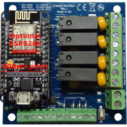
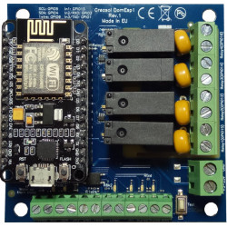


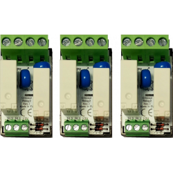

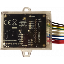
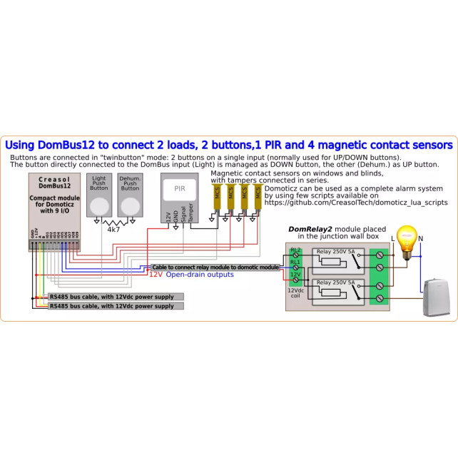
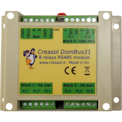
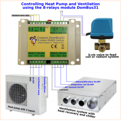
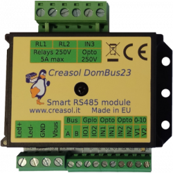

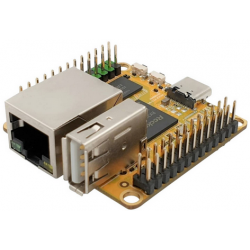


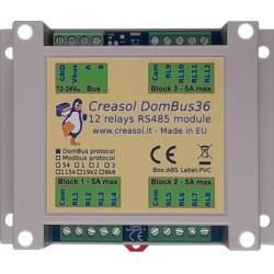


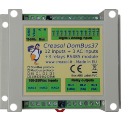
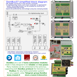

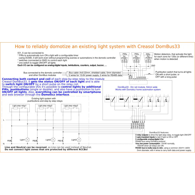

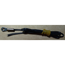
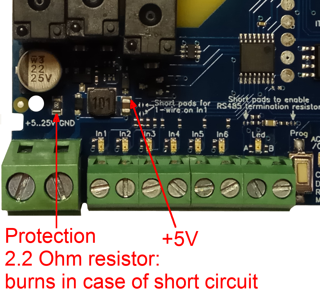